Aspar RS485 MODBUS Manuale utente

RS485 MODBUS Module 6TE
Expansion Module – 6 temperature inputs
Version 1 5 User Manual
Manufactured for

RS485 MODBUS Module 6TE
User Manual
Thank you for choosing our product.
This manual will help you with proper support and proper operation of the device.
The information contained in this manual have been prepared with utmost care by our
professionals and serve as a description of the product without incurring any liability for
the purposes of commercial law.
This information does not release you from the obligation of own judgment and
verification.
We reserve the right to change product specifications without notice.
Please read the instructions carefully and follow the recommendations contained
therein.
WAR I G!
Failure to follow instructions can result in equipment damage or impede
the use of the hardware or software.
Expansion Module – 6 temperature inputs
User Manual Version 1 5 2 / 16

RS485 MODBUS Module 6TE
User Manual
1. Safety rules
•Before first use, refer to this manual
•Before first use, make sure that all cables are connected properly
•Please ensure proper working conditions, according to the device specifications
(eg: supply voltage, temperature, maximum power consumption)
•Before making any modifications to wiring connections, turn off the power supply
2. Module Features
2.1. Purpose and description of the module
The 6TE module allows you to measure the temperature with attached popular
sensor Pt100, Pt500, Pt1000, i100, KTY81-110, TC (Carel) and thermocouple (type
J, K, T, , S, R, B). In addition, it is possible to measure voltages in the range 256mV
(10μV resolution) and to 2048mV (100μV resolution) as well as the measurement of
resistance to 8kΩ.
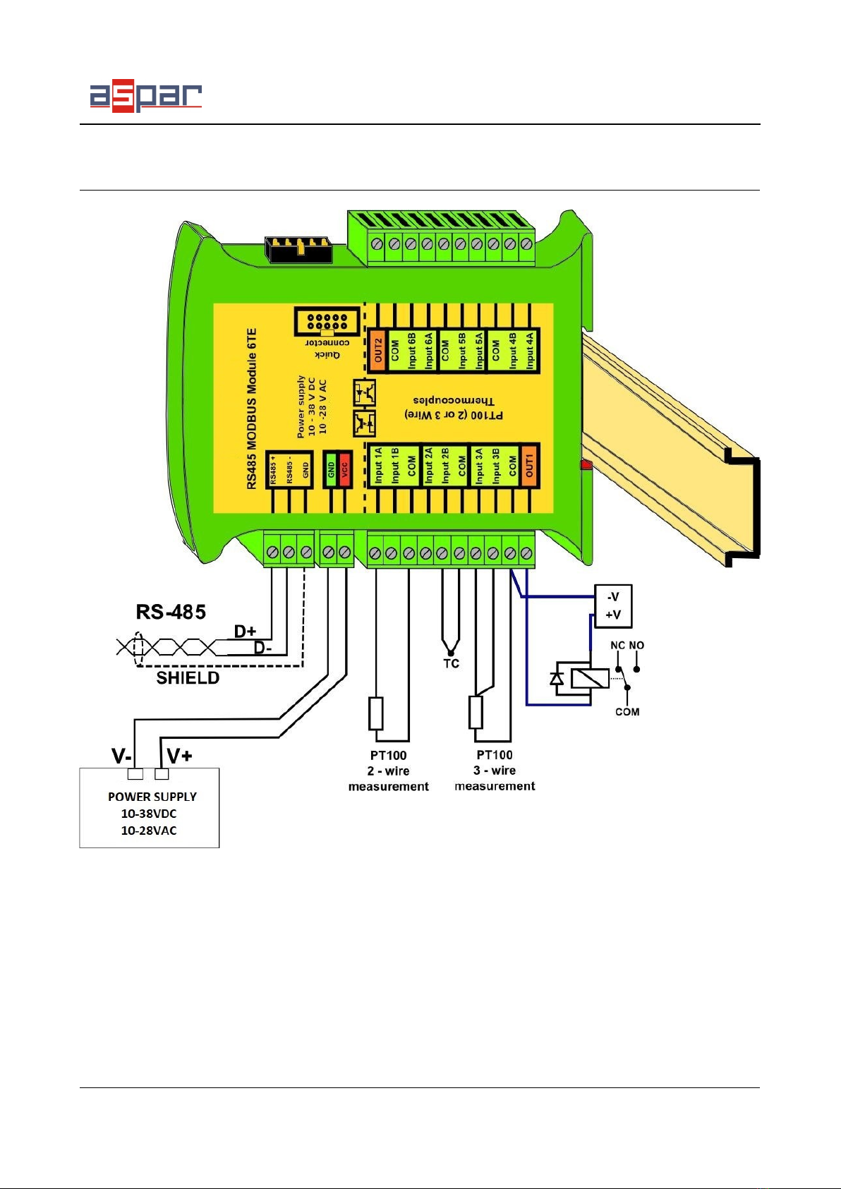
The device has a set of six inputs for the temperature measurement. It is possible
to 2- or 3-wire measurement of sensors Pt100, i100, Pt500, Pt1000 and 2-wire
measurement thermocouples and other sensors. In addition, the module is equipped with
2 configurable digital outputs (alarms).
Values are read via RS485 (Modbus), so we can easily integrate the module with
popular PLCs, HMI or PC equipped with the appropriate adapter.
This module is connected to the RS485 bus with twisted-pair wire.
Communication is via MODBUS RTU or MODBUS ASCII. The use of 32-bit ARM
core processor provides fast processing and quick communication. The baud rate is
configurable from 2400 to 115200.
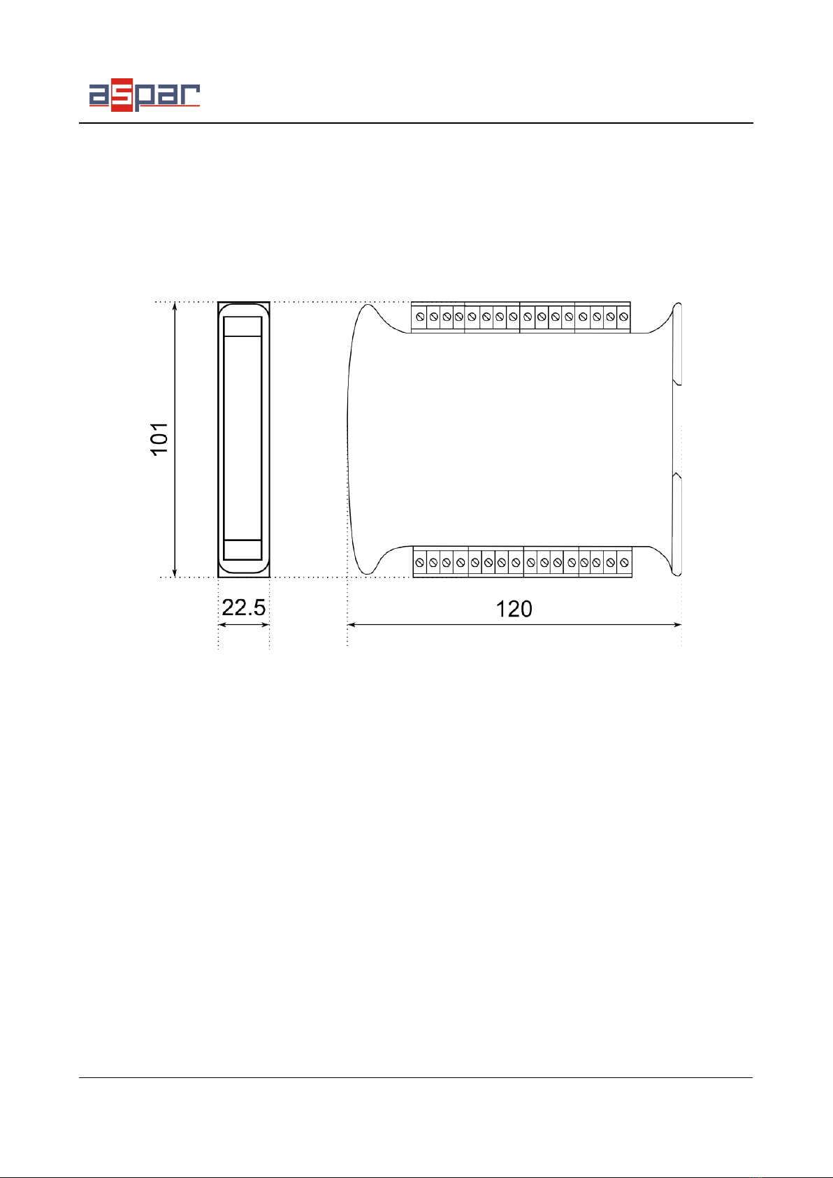
The module is designed for mounting on a DI rail in accordance with
DI E 5002.
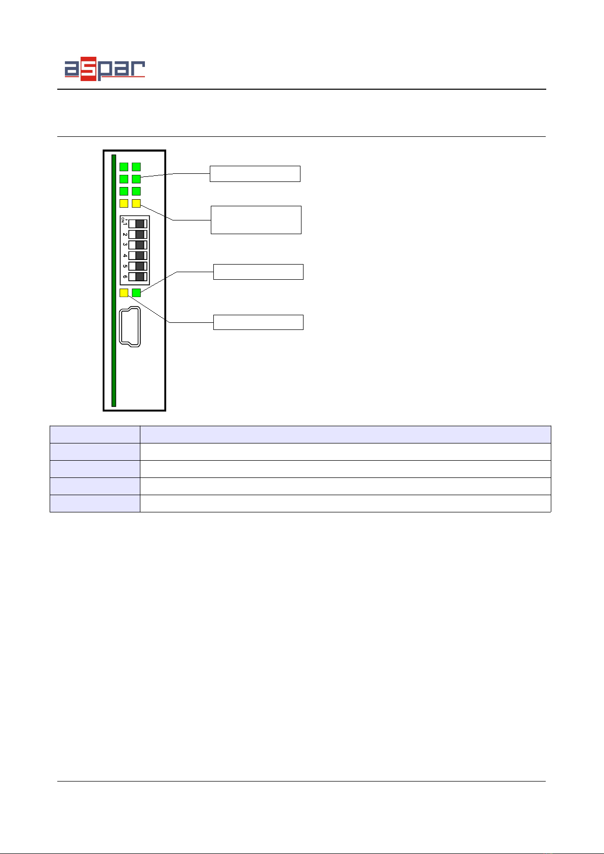
The module is equipped with a set of LEDs used to indicate the status of inputs
and outputs useful for diagnostic purposes and helping to find errors.
Module configuration is done via USB by using a dedicated computer program.
You can also change the parameters using the MODBUS protocol.
Expansion Module – 6 temperature inputs
User Manual Version 1 5 3 / 16

RS485 MODBUS Module 6TE
User Manual
2.2. Technical Specifications
Power Supply Voltage 10-38VDC; 10-28VAC
Maximum Current 120 mA 12V / 100 mA 24V
Inputs
No of inputs 6
Pt100 operation range -200°C - +850°C
Pt500 operation range -200°C - +850°C
Pt1000 operation range -200°C - +850°C
Ni100 operation range -60°C - +180°C
KTY81-110 operation range -55°C - +150°C
J thermocouple operation range -200°C - +1200°C
K thermocouple operation range -200°C - +1300°C
T thermocouple operation range -200°C - +400°C
N thermocouple operation range -200°C - +1300°C
S thermocouple operation range -0°C - +1700°C
R thermocouple operation range -0°C - +1700°C
B thermocouple operation range -0°C - +1800°C
Resistance From 0 to 8000Ω (1Ω resolution)
Voltage 0 to 2048mV (0,1mV resolution)
0 to 256mV (0,01mV resolution)
Measuring current ~250μA
Measurement resolution 0,1°C
Measurement error ±0,5°C
Cold junction temperature measurement -55°C - +100°C
Measurement error of the cold junction temperature ±1°C
ADC processing time 150ms / channel
Digital outputs Maximum current and voltage 500mA / 55V
Temperature Work -20 °C - +65°C
Storage -40 °C - +85°C
Connectors
Power Supply 2 pin
Communication 3 pin
Inputs and outputs 2 x 10 pin
Quick connector IDC10
Configuration Mini USB
Size
Height 120 mm
Length 101 mm
Width 22,5 mm
Interface RS485 Up to 128 devices
Expansion Module – 6 temperature inputs
User Manual Version 1 5 4 / 16

RS485 MODBUS Module 6TE
User Manual
2.3. Dimensions of the product
Look and dimensions of the module are shown below. The module is mounted
directly to the rail in the DI industry standard. Power connectors, communication and
IOs are at the bottom and top of the module. USB connector configuration and
indicators located on the front of the module.
Expansion Module – 6 temperature inputs
User Manual Version 1 5 5 / 16

RS485 MODBUS Module 6TE
User Manual
3. Communication configuration
3.1. Grounding and shielding
In most cases, IO modules will be installed in an enclosure along with other
devices which generate electromagnetic radiation. Examples of these devices are relays
and contactors, transformers, motor controllers etc. This electromagnetic radiation can
induce electrical noise into both power and signal lines, as well as direct radiation into
the module causing negative effects on the system. Appropriate grounding, shielding
and other protective steps should be taken at the installation stage to prevent these
effects. These protective steps include control cabinet grounding, module grounding,
cable shield grounding, protective elements for electromagnetic switching devices,
correct wiring as well as consideration of cable types and their cross sections.
3.2. Network Termination
Transmission line effects often present a problem on data communication
networks. These problems include reflections and signal attenuation.
To eliminate the presence of reflections from the end of the cable, the cable must
be terminated at both ends with a resistor across the line equal to its characteristic
impedance. Both ends must be terminated since the direction of propagation is bi-
directional. In the case of an RS485 twisted pair cable this termination is typically
120 Ω.
3.3. Setting Module ddress in RS485 Modbus Network
The following table shows how to set switch to determine the address of the
module. The module address is set with the switches in the range of 0 to 31. Addresses
From 32 to 255 can by set via RS485 or USB.
Addr SW5 SW4 SW3 SW2 SW1
0 OFF OFF OFF OFF OFF
1 OFF OFF OFF OFF ON
2 OFF OFF OFF ON OFF
3 OFF OFF OFF ON ON
4 OFF OFF ON OFF OFF
5 OFF OFF ON OFF ON
6 OFF OFF ON ON OFF
7 OFF OFF ON ON ON
8 OFF ON OFF OFF OFF
9 OFF ON OFF OFF ON
10 OFF ON OFF ON OFF
Addr SW5 SW4 SW3 SW2 SW1
11 OFF ON OFF ON ON
12 OFF ON ON OFF OFF
13 OFF ON ON OFF ON
14 OFF ON ON ON OFF
15 OFF ON ON ON ON
16 ON OFF OFF OFF OFF
17 ON OFF OFF OFF ON
18 ON OFF OFF ON OFF
19 ON OFF OFF ON ON
20 ON OFF ON OFF OFF
21 ON OFF ON OFF ON
Addr SW5 SW4 SW3 SW2 SW1
22 ON OFF ON ON OFF
23 ON OFF ON ON ON
24 ON ON OFF OFF OFF
25 ON ON OFF OFF ON
26 ON ON OFF ON OFF
27 ON ON OFF ON ON
28 ON ON ON OFF OFF
29 ON ON ON OFF ON
30 ON ON ON ON OFF
31 ON ON ON ON ON
Expansion Module – 6 temperature inputs
User Manual Version 1 5 6 / 16

RS485 MODBUS Module 6TE
User Manual
3.4. Types of Modbus Registers
There are 4 types of variables available in the module
Type Beginning
address Variable Access Modbus
Command
1 00001 Digital Outputs Bit
Read & Write 1, 5, 15
2 10001 Digital Inputs Bit
Read 2
3 30001 Input Registers Registered
Read 3
4 40001 Output Registers Registered
Read & Write 4, 6, 16
3.5. Communication settings
The data stored in the modules memory are in 16-bit registers. Access to
registers is via MODBUS RTU or MODBUS ASCII.
3.5.1. Default settings
You can restore the default configuration by the switch SW6 ( see 3.5.2 - Restore
the default configuration)
Baud rate 19200
Parity No
Data bits 8
Stop bits 1
Reply Delay [ms] 0
Modbus Type RTU
3.5.2. Restore the default configuration
To restore the default configuration:
•turn off the power
•turn on the switch SW6
•turn on the power
•when power and communication LED flash turn off the switch SW6
Caution! After restoring the default configuration all values stored in the registers will
be cleared as well.
Expansion Module – 6 temperature inputs
User Manual Version 1 5 7 / 16

RS485 MODBUS Module 6TE
User Manual
3.5.3. Configuration registers
Modbus Dec Hex Name Values
Address
40003 2 0x02 Baud rate
0 – 2400
1 – 4800
2 – 9600
3 – 19200
4 – 38400
5 – 57600
6 – 115200
other – value * 10
40005 4 0x04 Parity
0 – none
1 – odd
2 – even
3 – always 1
4 – always 0
40004 3 0x03 Stop Bits LSB 1 – one stop bit
2 – two stop bits
40004 3 0x03 Data Bits MSB 7 – 7 data bits
8 – 8 data bits
40006 5 0x05 Response delay Time in ms
40007 6 0x06 Modbus Mode 0 – RTU
1 – ASCII
Expansion Module – 6 temperature inputs
User Manual Version 1 5 8 / 16

RS485 MODBUS Module 6TE
User Manual
4. ndicators
Indicator Description
Power supply LED indicates that the module is correctly powered.
Communication The LED lights up when the unit received the correct packet and sends the answer.
Inputs state LED indicates that the sensor is connected.
Outputs state LED indicates that the output is on.
Expansion Module – 6 temperature inputs
User Manual Version 1 5 9 / 16
Power Supply
Communication
2 digital outputs
state
6 sensors state

RS485 MODBUS Module 6TE
User Manual
5. Module Connection
Expansion Module – 6 temperature inputs
User Manual Version 1 5 10 / 16
Altri manuali per RS485 MODBUS
3
Indice
Altri manuali Aspar Unità di controllo
Manuali Unità di controllo popolari di altre marche

Festo
Festo Compact Performance CP-FB6-E Manuale elenco delle parti

Elo TouchSystems
Elo TouchSystems DMS-SA19P-EXTME Manuale utente

JS Automation
JS Automation MPC3034A Manuale utente

JAUDT
JAUDT SW GII 6406 Series Guida rapida

Spektrum
Spektrum Air Module System Manuale utente

BOC Edwards
BOC Edwards Q Series Manuale utente


