AVPro Edge AC-EX40-444-KIT Manuale utente


Table of Contents
INTRODUCTION ���������������������������������������������������������������������������3
FEATURES �����������������������������������������������������������������������������������3
IN THE BOX ��������������������������������������������������������������������������������3
SPECIFICATIONS �������������������������������������������������������������������������4
THE TRANSMITTER �����������������������������������������������������������������������5
INDICATOR TROUBLESHOOTING LIGHTS - TRANSMITTER ������������������5
FUNCTIONS & SETUP OF THE TRANSMITTER ������������������������������������6
SETTINGS BUTTON - TRANSMITTER WITHOUT DIP SWITCHES ������������8
TEST PATTERN BUTTON - TRANSMITTER WITH DIP SWITCHES �����������9
THE RECEIVER ����������������������������������������������������������������������������9
INDICATOR TROUBLESHOOTING LIGHTS - RECEIVER ������������������������9
SETTINGS BUTTON - RECEIVER ���������������������������������������������������� 10
IR CONFIGURATION ������������������������������������������������������������������� 11
EXTRACTED AUDIO - L/R OUT ������������������������������������������������������ 13
AUDIO EXTRACTION EXAMPLE ����������������������������������������������������� 14
RS-232 PASS-THROUGH �������������������������������������������������������������� 14
TROUBLESHOOTING ������������������������������������������������������������������� 15
BANDWIDTH CHART ������������������������������������������������������������������� 15
MAINTENANCE �������������������������������������������������������������������������� 16
DAMAGE REQUIRING SERVICE ����������������������������������������������������� 16
SUPPORT ���������������������������������������������������������������������������������� 17
WARRANTY ������������������������������������������������������������������������������� 172
33Introduction
AVPro Edge presents its rst 18Gbps over copper extender. Using ICT (Invisible
Compression Technology) we have achieved what was thought to be impossible.
We can deliver a virtually lossless high bandwidth 4K HDR signal with support for
all signals up to 18Gbps. Deep Color and HDR Metadata remain intact making the
transmission free of artifacts like banding. Other similar devices will deliver a sub-par
image that has very visible banding and color shifting.
Features
·HDMI 2.0(a/b)
·18Gbps Bandwidth Support (Using ICT)
·Ultra Slim (.47 inch/12mm)
·Up to 4K60 4:4:4 Support
·Full HDR Support (HDR 10 & 12 Bit)
·HDR, HDR10+ and HLG Support
·4K --> 1080P Down-scaling for mixed systems
·EDID Management and EDID emulate
·4K & HD Test Patterns built into TX and Rx for
troubleshooting
·L/R Audio Extraction on TX and Rx
·HDCP 2.2 (and all earlier versions supported)
·CEC Pass Through
·3D Support
·70M (230ft) on 1080P (Cat6a)
·Up to 40m (131ft) on 4K (up to 4K60 4:4:4, HDR)
(Cat6a)
·Bi-directional 48v PoH (Power Over HDBaseT, only
one Power Supply Needed)
·I-Pass Feature for control system “pass-through”
·3-20v protection circuit built in for safe IR transport
·Bi Directional RS232 Transport
·LED Status, Link, Power indication lights
·Use single UTP/STP LAN cable (CAT-6A) with
substitute HDMI cable to achieve long distance
transmission.
·Supports uncompressed PCM 2- Ch., LPCM 5.1 &
7.1, Dolby Digital, DTS, Dolby TrueHD, DTS HD-
Master Audio, Atmos on HDMI
·ESD protection circuitry (Inputs & Outputs) to 7KV
·Can Cascade
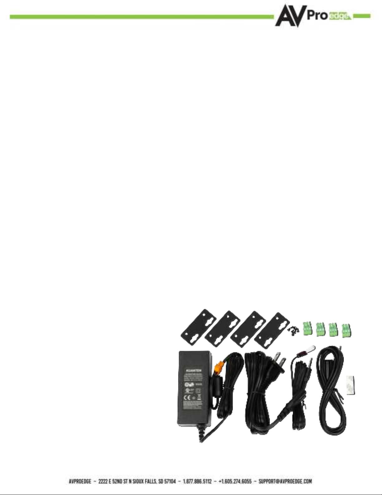
In The Box
·AC-EX40-444-T2 (Transmitter)
·AC-EX40-444-R (Receiver)
·48V Power Supply (One supplied) Power
either TX or RX
·1 x IR TX Unit
·1 x IR Rx Unit
·4x 3 Pin Terminal blocks for Audio and
RS232 Ports
·Mounting Brackets
*NOTE: Optional 3Pin to Stereo Audio Cables available for purchase AC-CABLE-3PIN-2CH

4Specications

5The Transmitter
Indicator Troubleshooting Lights - Transmitter
POWER - On the back by power supply input: (Red) This is an indicator that the
power is connected. There are only two states for light:
·Light Is On = Power supply is connected and functioning.
·Light Is O = Power supply is not connected or there is no power present.(In order to have
power: check the power supply, USP, Outlet, etc...)
STATUS - On front by HDMI Port: (Blue) This indicator shows that the HDMI
source is connected. The states are:
·Light Is On (Solid) = Sync w/ HDMI source is correct and solid.
·Light Is Flashing = The light ashes during the sync process. If it is ashing continuously, a
picture may not be present.
If the BLUE HDMI STATUS LIGHT is ashing, check the following:
1. The source. Plug it directly into the display to be sure it’s functioning properly.
2. Try a longer HDMI cable. Some HDMI cables do not sync well at shorter lengths, a 2 meter
HDBaseT RS-232
IR
Mode
Micro USB
(Firmware)
L/R Out
(PCM Only)
IR OUT IR IN
HDMI In
EDID/Scaler
Settings
See Page(s) 7
Test Pattern
Enable/Disable
Power

6LINK - Above RJ45 (HDBT) Port: (Green) This indicator shows that the AV HDBT
link between the TX and Rx is in tact. This light should ALWAYS be solid. If this light is
ashing or not present attempt following:
1. Check the length. The maximum distances are 40m (131ft) on 4K and 70m (230ft) on 1080P.
2. Remove any coils of cable and make sure that there is not excess cabling.
3. Bypass all patch panels and punch-down blocks.
4. Re-terminate connectors. Sometimes, even if a cable tester indicates the run is valid, something
may be slightly o.
a. Standard RJ45 ends are recommended. Pass through style types can cause interference/
crosstalk.
5. Contact AVProEdge if these suggestions do not work.
STATUS- Above RJ45 (HDBT) Port: (Amber) This is an indicator showing that the
power is present between the Transmitter and Receiver. This light ALWAYS BLINKS
steadily indicating everything is OK. If you do not see this light, attempt the following:
1. Check the length. The maximum distances are 40m (131ft) on 4K and 70m (230ft) on 1080P.
2. Remove any coils of cable and make sure that there is not excess cabling.
3. Bypass all patch panels and punch-dovwn blocks.
4. Re-terminate connectors. Sometimes, even if a cable tester indicates the run is valid, something
may be just slightly o.
a. Standard RJ45 ends are recommended. Pass through style types can cause interference/
crosstalk
5. Try powering from the Receiver instead of the Transmitter (See Receiver page for more about
PoE direction).
6. Contact AVProEdge if these steps do not work. Contact AVProEdge if these suggestions do not
work.
Functions & Setup of the Transmitter
IR Mode Slide Switch: (On Back) This is used to select a preferred IR Mode for the
IR IN port. The two options are:
·IR-EYE - The IR Input will be congured to operate with an IR Receiver Eye.
·I-PASS - The IR Input will be congured to safely operate with a direct connection from a control
system using a mono or stereo 3.5mm cable. This is protected from 3v-20v. Default mode is IR-
EYE.
minimum is recommended per HDMI Specications.
3. Set the EDID to state #1 (See Page[s] 7).
4. If these suggestions do not work, enable the “Test Pattern” (See Page[s] 8). If you see the
pattern, the problem is between the source and the Transmitter, please try a dierent source.
5. Contact AVProEdge if these suggestions do not work.

7EDID Management: GEN2 (pre DIP Switches)
Press the SETTINGS button to cycle through the EDIDs
4 LED lights on the board inside the chassis (see below)
·Solid LED = ON
·Flashing LED = OFF
Copy EDID: To COPY EDID from Sink Device, press the settings button until only LED #4 is lit up
(USER EDID). With the Sync Device powered on and the USER EDID Slot selected, press and hold
the settings button for approximately 5 seconds to copy and save that EDID. The red POWER LED will
ash conrming copy successful.
NOTE: If you press and hold the SETTINGS button in any other state besides USER EDID,
this will enable/disable the 4K to 2K Down-Scaler�
EDID Management:GEN2 (NEW FOR 2022) with DIP
Switches on the bottom of the Transmitter
The rst 3 are used to set the EDID
·OFF/UP/0
·ON/DOWN/1
Examle set to
EDID BYPASS
(Default)

8Settings Button - Transmitter without Dip
Switches
Use this button to Enable the built in 1080P Color Bar Test pattern.With the Power unplugged from the Transmitter, hold the SETTINGS button while plugging the Power back in. To Disable the built in Color Bar Test pattern power cycle the Transmitter (remove the power for 3 seconds then plug back in).1920x108P @60Hz
Copy EDID: To COPY EDID from Sink Device move DIP Switches 1, 2, and 3 from OFF (up) to ON (down) at the same time while connected Sync is powered on. The EDID will be saved until this process is repeated (move 1, 2, and 3 all back to ON, then all 3 back to OFF).
NOTE: Moving DIP 4 does not aect the COPY EDID function. You can use a coin or other
at object to move all the dip switches together, then once copied move DIP 4 back to
desired position if needed�
DIP Switch 4 is used to set the Down-Scaler
·OFF/UP/0 = Scaler Bypass/OFF
·ON/DOWN/1 = All 4K signals will be down-scaled to 2K

9The Receiver
Indicator Troubleshooting Lights - Receiver
POWER - On the back by power supply input: (Red) This is an indicator that the
power is connected. There are only two states for light:
·Light Is On = Power supply is connected and functioning.
Light Is O = Power supply is not connected or there is no power present. In order to have power:
check the power supply, POE Switch on Reviver, USP, Outlet, etc...
HDBaseT RS-232
POE
Mode
Micro USB
(Firmware)
L/R Out
(PCM Only)
IR OUT IR IN
HDMI OUT
Test Pattern
Enable/Disable
Power
Test Pattern Button - Transmitter with Dip
Switches
Use this button to Enable/Disable the built in 1080P Color Bar Test pattern.Press once to Enable, press again to Disable.NOTE: The Reciever also has built in test pattern generator� See page 10 for more details�
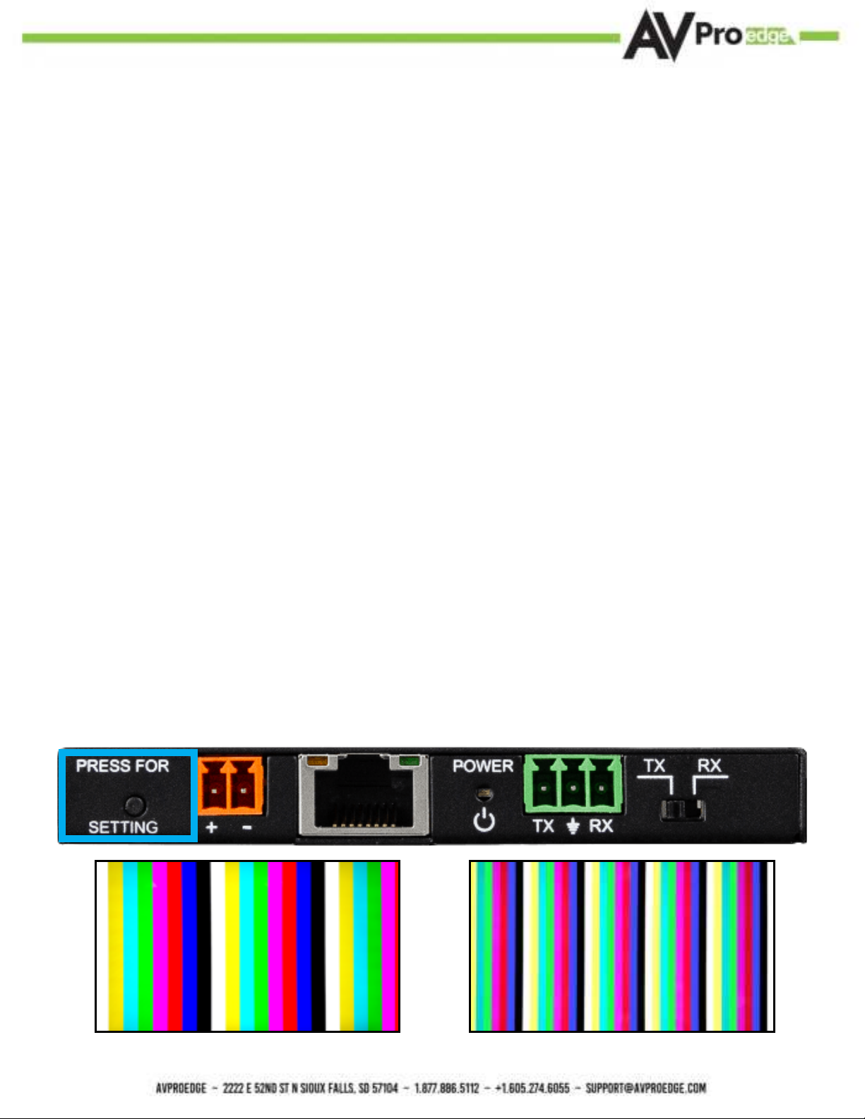
10Settings Button - Receiver
Use this button to Enable/Disable the built in Color Bar Test pattern, there are three available settings.Press once to Enable the 2k test pattern, press again to Enable the 4k test pattern, press a third time to disable.3840x2160P @30Hz1920x1080P @60Hz
STATUS - On front by HDMI Port: (Blue) This indicator shows that the HDMI sink is
connected. The states are:
·Light Is On (Solid) = Sync w/ HDMI sink is correct and solid.
·Light Is Flashing = The light ashes during the sync process. If it is ashing continuously, a
picture may not be present.
If the BLUE HDMI STATUS LIGHT is ashing, check the following:
1. The source. Plug it directly into the display to be sure it’s functioning properly.
2. Try a longer HDMI cable. Some HDMI cables do not sync well at shorter lengths, a 2 meter
minimum is recommended per HDMI Specications.
3. If these suggestions do not work, enable the “Test Pattern” (See Page[s] 8). If you see the
pattern, the problem is more than likely between the source and the Transmitter, please try a
dierent source.
4. Contact AVProEdge if these suggestions do not work.
Questo manuale è adatto per i seguenti modelli
2
Indice
Altri manuali AVPro Edge Trasmettitore

AVPro Edge
AVPro Edge ConferX AC-CXWP-HDMO-T Manuale utente

AVPro Edge
AVPro Edge AC-EX100TT-UHD-T Manuale utente

AVPro Edge
AVPro Edge AC-CXWP-HDMO-BKT Manuale utente

AVPro Edge
AVPro Edge AC-CXWP-HDMO-T Manuale utente

AVPro Edge
AVPro Edge AC-CXWP-VGA-T Manuale utente

AVPro Edge
AVPro Edge AC-AEX-KIT Manuale utente

AVPro Edge
AVPro Edge AC-CXWP-USBC-T Manuale utente


