Bay Networks BayStack Fiber Media Adapter Guida

March 1996
893-863-A
Bay Networks, Inc. Corporate Headquarters
4401 Great America Parkway
Santa Clara, CA 95054 8 Federal Street
Billerica, MA 01821
Using the BayStack
Ethernet Redundant
Fiber Media Adapter

© 1996 by Bay Networks, Inc. All rights reserved.
Trademarks
Bay Networks, BayStack, and Bay Networks Press are trademarks of Bay
Networks, Inc. Other brand and product names are registered trademarks or
trademarks of their respective holders.
Statement of Conditions
In the interest of improving internal design, operational function, and/or reliability,
Bay Networks, Inc. reserves the right to make changes to the products described in
this document without notice. Bay Networks, Inc. does not assume any liability that
may occur due to the use or application of the product(s) or circuit layout(s)
described herein.
Related Publications
For more information about the installation and use of BayStack
TM
hubs and
optional equipment, refer to the following publications:
•
Using the BayStack 10BASE-T Hubs
(Bay Networks
TM
part number 893-839-B)
•
Using the BayStack Ethernet Network Management Modules
(Bay Networks part number 893-841-A)
Ordering Bay Networks Publications
To purchase additional copies of this document or other Bay Networks publications,
order by part number from Bay Networks Press
™
at the following numbers.You
may also request a free catalog of Bay Networks Press product publications.
• Phone: 1-800-845-9523
• FAX: U.S./Canada: 1-800-582-8000, International: 1-916-939-1010

893-863-A 1
Introduction
This guide describes the Bay Networks 10BASE-FL RDN Media
Adapter for the BayStack 10BASE-T Hubs and provides
instructions for installing, connecting, and configuring the
adapter in the hub.
Each BayStack 10BASE-FL RDN MediaAdapter consists of one
optional 10BASE-FL port that provides flexible, redundant
backbone connectivity and two diagnostic LEDs.
This guide contains the following sections:
• BayStack 10BASE-FL RDN Media Adapter
• LEDs
• Jumper
• Remote Signaling
• Redundant Links
• Fiber Optic Cable Length Limitations
• Installing a Media Adapter in a BayStack Hub
For more information about how the media adapter operates in
the hub, refer to
Using the BayStack 10BASE-T Hubs
(Bay
Networks part number 893-839-B). For more information about
hub compatibility with the 10BASE-FL RDN Media Adapter,
refer to
Release Notes for the BayStack 10BASE-T Hubs
(Bay
Networks part number 896-086-A).

2 893-863-A
BayStack 10BASE-FL RDN Media Adapter
The BayStack 10BASE-FL RDN Media Adapter is a modular
10BASE-FL port.
The port is compatible with the IEEE 802.3 10BASE-FL
specification for Ethernet running over 62.5/125
µ
m or
50/125
µ
m multimode fiber optic cable.
10BASE-FL (fiber link) asynchronous signaling is fully
interoperable with fiber optic interrepeater link (FOIRL). Remote
signaling and redundant links are also supported. The redundant
10BASE-FL media adapter provides Rem (remote) and Rdn
(redundant) status LEDs. Jumpers allow you to set remote and
redundant link configuration.
Connection is made to the port using two fiber optic straight-tip
(ST) connectors (Tx and Rx).
For more information on fiber optic cable connection and
limitation, see “Fiber Optic Cable Length Limitations” later in
this guide.
5957
Rem
Rdn
TX
10BASE-FL RDN
RX

893-863-A 3
LEDs
The BayStack 10BASE-FL RDN Media Adapter provides LEDs
to indicate remote signaling and redundant link status. These
LEDs are used in combination with the BayStack 10BASE-T
Hub “Media Adapter” LED to indicate the status of the active
and standby link.
Table 1 describes the redundant 10BASE-FL media adapter
LEDs.
Table 1. 10BASE-FL RDN Media Adapter LEDs
Label Color Meaning
Rem Green Fiber port is connected to a remote port that uses
remote signaling, and that port is not sending a
remote fault signal; both Tx and Rx connections
are good.
Amber Fiber port is connected to a remote port that uses
remote signaling, but the Tx link to the remote Rx
connector detects a remote fault.
Off Fiber port is not connected to another port that is
capable of remote signaling.
Rdn Green Port is in redundant mode and detects no fault.
Amber Port is in redundant mode, but this redundant port
connection has failed.
Off Port is not in redundant mode.

4 893-863-A
Table 2 describes the LED combinations of the hub “Media
Adapter” LED and the redundant fiber media adapter LEDs.
Remote Signaling
The BayStack 10BASE-FL RDN MediaAdapter supports remote
signaling to indicate a far end receiver failure/remote fault
detection. Bay Networks uses a proprietary version of remote
fault signaling, because remote signaling is not specified in the
IEEE 802.3 10BASE-FL standard. Remote signaling is used to
verify the connection status of both the transmit and receive
fibers.
A Rem LED on the media adapter indicates remote signaling
status. For more information about this LED, see “LEDs” earlier
in this guide.
Table 2. LED status combinations
Hub LED Rem Rdn Meaning
Green Green Green Active link in a redundant port pair; link
status is good, and remote link is good.
Amber Green Green Standby link in a redundant pair; link status
is good, and remote link is good.
Amber Green Amber Standby link in a redundant pair is
partitionedornotready;remotelinkisgood,
but port is partitioned by detection of a local
fault (or possibly network management).
Amber Amber Amber Standby link in a redundant pair is
partitioned for remote fault; check Tx link.
Off Off Amber Standby link in a redundant pair has failed
connection; check Tx and Rx links.

893-863-A 5
Redundant Enable Jumper
Jumper JP1 is used to set the port to operate in the redundant port
mode. The 10BASE-FL RDN Media Adapter is shipped with the
redundant port mode set to off.
To set the port to operate in the redundant port mode, perform the
following steps:
• Locate the shunt covering the JP1 jumper pins on the media
adapter board.
• Gently remove the shunt from the two far left pins.
• Replace the shunt over the two far right pins.
NOTE:
Jumpers JP2, JP3, and JP4 are not
user-configurable.
Jumper 1
RDN EN
JP1 JP1
RDN EN
Default
mode Redundant
mode
6771
6 893-863-A
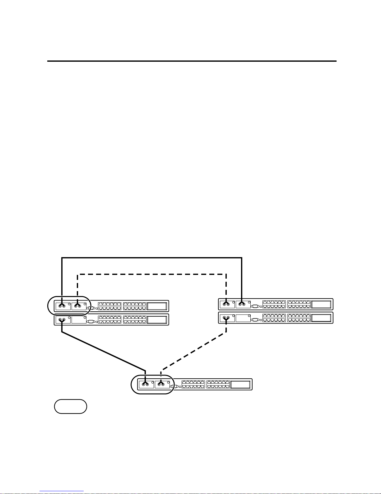
Redundant Links
The BayStack 10BASE-FL RDN Media Adapter supports
redundant links between Bay Networks BayStack Ethernet hubs,
System 5000 hubs, and other Bay Networks hubs that support
redundant links. If one fiber connection in a redundant pair
breaks, the standby link automatically takes over in less than 10
microseconds. This redundant link feature allows you to build
Ethernet dual-homing and mesh-type topologies. The port at both
ends of the fiber connection must support Bay Networks remote
signaling.
A jumper is used to set the redundant 10BASE-FL media adapter
port to operate in redundant mode with a 10BASE-FL fiber port
on another hub.
Active fiber link (Tx/Rx pair)
Standby fiber link (Tx/Rx pair)
= Redundant pairs
5977

893-863-A 7
For a pair of ports to operate in redundant mode:
• Enable the JP1 jumper for redundant port mode on both of
the media adapters in the redundant port pair. For more
information about this jumper, see “Redundant Enable
Jumper” earlier in this guide.
• Disable any redundant port mode on the port at the other end
of each redundant link.
A Rdn LED media adapter indicates redundant link status. For
more information about this LED, see “LEDs” earlier in this
guide.

8 893-863-A
Fiber Optic Cable Length Limitations
The 10BASE-F standard permits you to use fiber optic cables up
to 2000 meters long. However, the fiber connection must meet
the following criteria:
• Optical power budget (shown in Table 3)
• Ethernet repeater rules
For more information about simple rules for Ethernet network
compliance, refer to
Using the BayStack 10BASE-T Hubs
.
The optical power budget is shown in Table 3. Power loss in the
link cannot exceed the value for the type of fiber optic cable you
are using.
Only in-line fiber-to-fiber connections (a connection between
two fibers terminated with fiber connectors, using a fiber-to-fiber
connector) count against the optical power budget. The loss in a
fiber connection at the ends of the link are included in the optical
power budget and does not count as an in-line connection.
Table 3. 10BASE-FL RDN Media Adapter Power Budget
Parameter 62.5/125
µ
m 50/125
µ
m
Transmitted power (average) –20 dBm –25.7 dBm
Receiver sensitivity (average) –32.5 dBm –32.5 dBm
Optical power budget 12.5 dB 6.8 dB
Indice
Manuali Scheda di rete popolari di altre marche


Buffalo
Buffalo AirStation WLI-PCM-L11GP Manuale utente

National Instruments
National Instruments NI 9234 Manuale utente

Hama
Hama 49276 Manuale utente

Linksys
Linksys WCF54G - Wireless-G Compact Flash Card Manuale operativo

Compaq
Compaq Wireless LAN 100 Manuale utente

Bose
Bose PowerMatch Dante Manuale utente