S-Bt Service Manual - V.1AW Version 1 - October 2017 Page 9
21. To replace the Fan:
– open the door and remove shelves, unscrew the two screws (fig.14/1)
and remove chamber cover;
– unscrew the two screws 10 6 and release Fan wires;(fig. /)
– remove UV lamp (see UV lamp replacement);
– disconnect UV lamp wires from ballast (see ballast replacement);
– unscrew the screws 15 4 and release lamp holder bracket;(fig. /)
– unscrew the two nuts 15 3 and release Fan holder bracket;(fig. /)
– loosen wire transfer port;
– pull out Fan holder bracket and unscrew the four screws 15 5 of (fig. /)
malfunctioning Fan;
– replace the Fan and re-assemble the unit.
22. To replace the Chamber Temperature Sensor:
– open the door and remove shelves, unscrew the two screws (fig.14/1)
and remove chamber cover;
– remove Temp. Sensor insulation layer (fig.9/2);
– release Chamber Temperature Sensor wires from the power board;
– unscrew the 1 6 and Chamber Temperature Sensor nut (fig. 5/ )remove
assembly;
– replace Chamber Temperature Sensor assembly;
– re-assemble the unit;
23. To replace the Back Temperature Sensor:
– remove the power board (see power board replacement);
– remove the sensor interface board (see sensor interface board
replacement);
– unscrew the four screws (fig.10/10) and remove rear cover;
– remove heat insulation layer (fig.11/6);
– unscrew the appropriate two screws (fig.8/1) and remove cover and
cushion;
– remove heat shrink sleeve (fig.8/2);
– desolder Temperature Sensor wires and remove it;
– solder new Temperature Sensor (1. scheme);
– re-assemble the unit.
24. To replace the Back Heater:
– remove the power board (see power board replacement);
– remove the sensor interface board (see sensor interface board
replacement);
– unscrew the four screws (fig.10/10) and remove rear cover;
– remove heat insulation layer (fig.11/6);
– remove back temperature sensor (see back temperature sensor
replacement);
– tear off Back Heater;
– replace the Heater and re-assemble the unit.
Disassembling for the: Transformer, Port Heater, Bottom
Temperature Sensor, Perimeter Temperature Sensor.
1. Disconnect the unit from power supply.
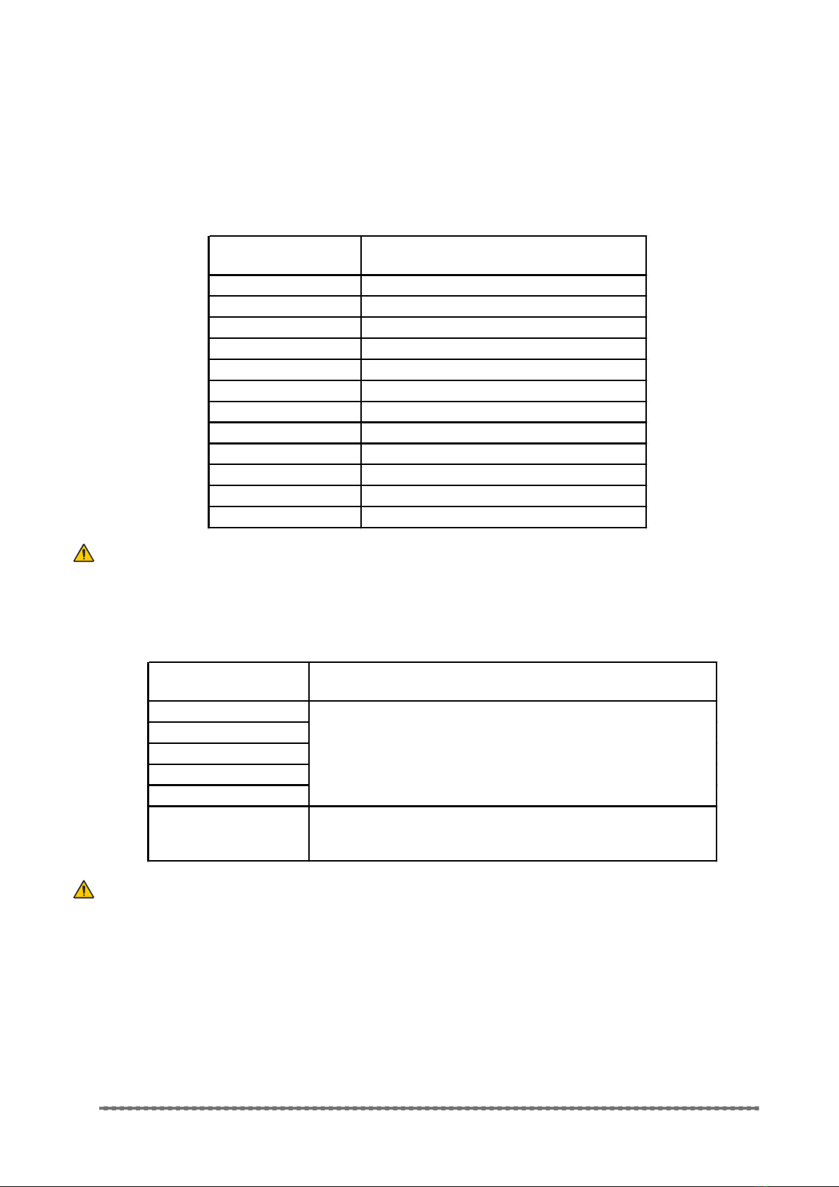
2. Turn the unit upside down.
3. Unscrew the sixteen screws fig(16/1).
4. Turn around underside cover and unscrew one screw to release
ground wire, remove cover.
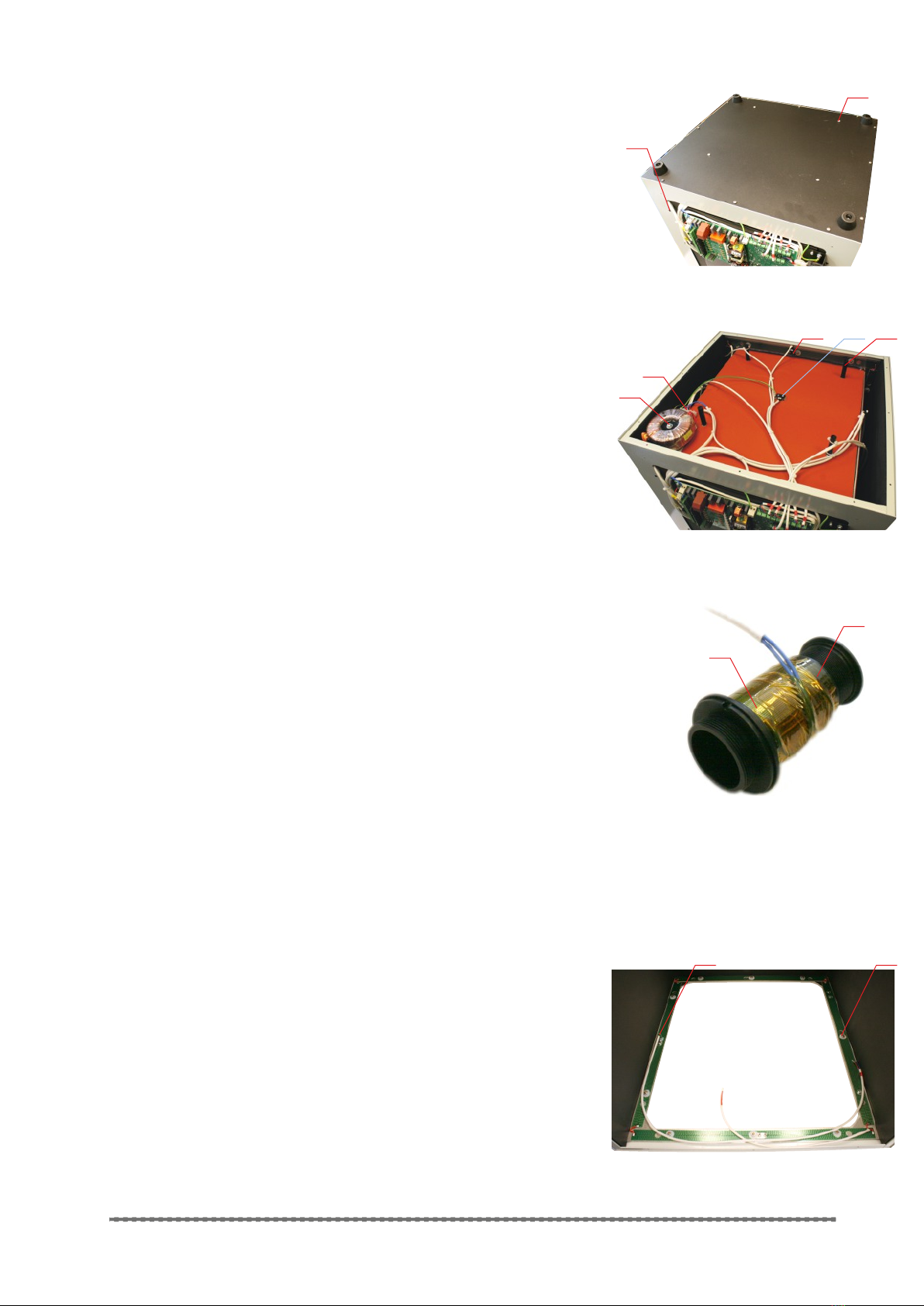
25. To replace the Transformer:
– mark the wires with appropriate connection slots;
– unscrew the five screws and release Transformer wires from wire
terminal (fig.17/1);
– unscrew the screw (fig.17/2) and release the Transformer;
– replace the Transformer and re-assemble the unit.
fig.12M
UV lamp ballast
12
1
2
fig.13M
Power socket
3
4
1
12
fig.14M
Opened door
fig.15M
Chamber cover removed
3 45 6
7
2