BLB hydraulic BM20 Manuale utente

UPGRADE YOUR HYDRAULIC CONTROL
BM20
MONOBLOCK
DIRECTIONAL
CONTROL VALVES
SOUPAPE DE COMMANDE
DIRECTIONNELLE
MONOBLOC BM20
INSTRUCTIONS MANUAL

BM20 MONOBLOCK DIRECTIONAL CONTROL VALVES / INSTRUCTIONS MANUAL
2
ITEM 8669673 – 902457 BM20/1 ZB FU /MO A1/
Installation Dimensions / Dimensions d’Installation

3
BM20 MONOBLOCK DIRECTIONAL CONTROL VALVES / INSTRUCTIONS MANUAL
ITEM 8669681 – 902458 BM20/2 ZB FU /MO A1/MO A1/
Installation Dimensions / Dimensions d’Installation

BM20 MONOBLOCK DIRECTIONAL CONTROL VALVES / INSTRUCTIONS MANUAL
4
ITEM 8669699 – 902459 BM20/3 ZB FU /MO A1/MO A1/MO A1/
Installation Dimensions / Dimensions d’Installation

BM20 MONOBLOCK DIRECTIONAL CONTROL VALVES / INSTRUCTIONS MANUAL 5
PRESSURE DROP
BM20 TECHNICAL SPECIFICATIONS
Work Flow / Max Flow 4.5 GPM / 6.6 GPM
Relief valve setting 2,100 PSI
Relief valve range 1,300 to 3,600 PSI
Inlet/Outlet Ports 8 ORB Side / 6 ORB Top
Work Ports 6 ORB
BM20 MAIN FEATURES
Zinc plating protects against corrosion and rust
Precise ow metering to accurately control actuator speed
Power beyond capability for easy addition of valves
downstream
Easy to convert from Open to Closed center
Customizable with a variety of spool and positioner options
0
50
100
150
200
250
0 2 4 6 8 10 12
PRESSURE (psi)
FLOW (gpm)
/1
/2
/3
BM20 A-T PRESSURE DROP
B
A
T
3 2 1
0
50
100
150
200
250
0 2 4 6 8 10 12
PRESSURE (psi)
FLOW (gpm)
/3
/2
/1
BM20 P-A PRESSURE DROP
P
B
A
1 2 3
0
50
100
150
200
250
0 2 4 6 8 10 12
PRESSURE (psi)
FLOW (gpm)
3
2
1
BM20 P-T PRESSURE DROP
P
1 2 3
T
B
A
T
3 2 1
P
B
A
1 2 3
P
1 2 3
T

BM20 MONOBLOCK DIRECTIONAL CONTROL VALVES / INSTRUCTIONS MANUAL
6
PARTS LIST:
Drawing 1
BM20 SPARE PARTS
Nº Parts Parts Nº sub part Sub part
1Relief Valve kit 1.1 Screw
1.2 Nut
2 Check valve
3 Kit handle
4 Handle cap kit 4 Handle cup
4.1 Screw
5 Spool kit 5.1 Seal
5 Spool
6 Positioner kit
6 Positioner cap
6.1 Positioner kit
6.2 Screw
1.1 1.2
1
2
3
4.1
4
5
5.1
6.1
6
6.2

BM20 MONOBLOCK DIRECTIONAL CONTROL VALVES / INSTRUCTIONS MANUAL 7
EN
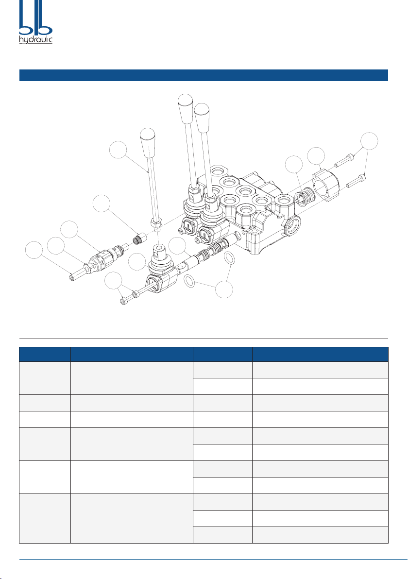
CHANGING THE VALVE SPOOL AND SEALS (See drawing 1):
Step 1. Remove the Handle (Part 3).
Step 2. Remove the Bolts (Part 6.2) with a 5mm hex key and remove the Positioner Cap (Part 6).
Step 3. Using a 5mm hex key remove the positioner (Part 6.1).
Step 4. Remove the bolts (Part 4.1) with a 5mm hex key and remove the Handle Cap (Part 4).
Step 5. Always start on the Positioner Cap side when removing the O-rings. Move the Spool (Part 5) only far enough to expose the
O-ring (Part 5.1). Be careful not to push the spool too far past the O-ring groove as this will cut the O-ring on the Handle Cap
side. Remove the O-ring with a pick.
Step 6. Remove the spool through the Positioner Cap end of the valve. Remove the Handle Cap side O-ring with a pick.
Step 7.
Lightly oil the new spool with clean hydraulic uid. Insert the spool into the valve and push and pull it within the valve casting to make
sure there is very little resistance. If resistance is felt please try a new spool to eliminate binding.
Step 8. Push the spool back on the Handle Cap end so the O-ring can be installed in the groove.
Step 9. After the O-ring is installed in the Handle Cap end slowly push the spool from the Positioner Cap end to expose the O-ring
groove. Be careful not to push the spool too far past the O-ring groove as this will cut the O-ring on the Handle Cap side.
Install the O-ring in the groove.
Step 10. Install the Handle Cap rst and tighten the bolts to 6.3 ft. lbs.
Step 11. Install the Positioner into the spool and tighten to 9.6 ft. lbs.Then install the Positioner Cap and tighten the bolts to 6.3 ft. lbs.
Step 12. Add the Handle to the valve and move it back and forth to see if you feel any sticking of the spool. If it is not sticking the
installation is complete.
If it feels like it’s sticking, loosen the Caps and realign, then try it again, this should x the sticking issue.
CHANGING THE SPRING POSITIONER TO DETENT POSITIONER (See drawing 1):
Step 1. Remove the bolts (Part 6.2) with a 5mm hex key and remove the Positioner Cap (Part 6).
Step 2. Using a 5mm hex key remove the old Positioner (Part 6.1).
Step 3. Install the new Positioner into the Spool and tighten to 9.6 ft. lbs.
Step 4. Install the Positioner Cap and tighten the bolts to 6.3 ft. lbs.
SETTING THE RELIEF VALVE
An adjustable relief valve is standard on all monoblock directional valves. Standard factory setting is 2,100 PSI.
The relief pressure is adjusted by releasing the Nut (Part 1.2), and turning the Adjusting Screw (Part 1.1) with a 4 mm hex key wrench.
Turning the Adjusting Screw clockwise will increase the pressure and counter-clockwise will decrease the pressure (a pressure gauge
must be installed in the inlet line whenever the relief pressure is adjusted). Adjustable pressure range is 1,300 PSI to 3,600 PSI. Do not
backout adjusting screw to the point it falls out.

BM20 MONOBLOCK DIRECTIONAL CONTROL VALVES / INSTRUCTIONS MANUAL
8
OPTIONAL
Power Beyond Adapter (CO)
Closed Center Plug (CCP)
Relief Valve Plug (RVP)
A
A
RVP
B
B
CO
A
A
CCP
HOW TO INSTALL POWER BEYOND ADAPTER (CO)
Step 1. Screw the power beyond adapter into the T2 port with 22 mm
hex wrench and tighten to 18 ft. lbs. When the Power Beyond
Plug is installed a hose must be attached to the T1 port and
run back to the reservoir. Failure to do this will cause the valve
not to function properly.
HOW TO INSTALL CLOSED CENTER PLUG (CCP)
Step 1. Screw the Closed Center Plug into the T2 port with 8 mm hex
key and tighten to 29.5 ft. lbs.When the Closed Center Plug is
installed a hose must be attached to the T1 port and run back
to the reservoir. Failure to do this will cause the valve not to
function properly.
HOW TO INSTALL RELIEF VALVE PLUG (RVP)
Step 1. Remove the Relief Valve (Part 1) whit a 22 mm wrench.
Step 2. Take out the load Check Valve (Part. 2) and install on the relief
valve plug
Step 3. Screw the Relief Valve Plug into the Relief Valve port with 8
mm hex key and tighten to 44 ft. lbs.

BM20 MONOBLOCK DIRECTIONAL CONTROL VALVES / INSTRUCTIONS MANUAL 9
EN
WARNING
• All hydraulic valves must be properly installed into the hydraulic system to prevent personal injury and/or property damage. Further,
the improper servicing of a valve may result in personal injury and/or property damage. Please read and understand all catalogue
and service information before starting, as with all mechanical work the proper tools, knowledge, and safety equipment are required,
always wear safety glasses.
• Make sure all pressure has been relieved in the hydraulic lines before installing or servicing a hydraulic valve.
• Escaping hydraulic uid under pressure can have sufcient force to penetrate skin, causing serious personal injury. Do not use your
hand to check for hydraulic leaks.
• Before installing or servicing a hydraulic component make sure all weight has been removed from the cylinders or motors before
disconnecting hydraulic lines.
• Disconnecting the hydraulic lines while the cylinder or motor is under load may result in the unexpected rapid movement of machine
resulting in serious personal injury.
• Do not exceed the operating specications for pressure, ow or temperature, all hydraulic systems require a means to limit the
maximum pressure. This requires either a pressure relief valve in the system or a pump that has pressure compensation.
• Overpressure may cause sudden and unexpected failure of a component in the hydraulic system resulting in serious personal injury,
always use a gauge when adjusting a relief valve.

BM20 MONOBLOCK DIRECTIONAL CONTROL VALVES / INSTRUCTIONS MANUAL
10
Indice
Lingue:
Altri manuali BLB hydraulic Unità di controllo
Manuali Unità di controllo popolari di altre marche

Festo
Festo Compact Performance CP-FB6-E Manuale elenco delle parti

Elo TouchSystems
Elo TouchSystems DMS-SA19P-EXTME Manuale utente

JS Automation
JS Automation MPC3034A Manuale utente

JAUDT
JAUDT SW GII 6406 Series Guida rapida

Spektrum
Spektrum Air Module System Manuale utente

BOC Edwards
BOC Edwards Q Series Manuale utente


