CIRCUIT DESIGN MU1-UIK Manuale utente

OG_MU1_UIK_v20e
OPERATION GUIDE
Embedded low power radio modem MU-1
MU-1 USB Interface Kit
MU1-UIK
Operation Guide
Version 2.0 (May 2005)
CIRCUIT DESIGN, INC.,
7557-1 Hotaka, Hotaka-machi,
Minamiazumi, Nagano 399-8303 JAPAN
Tel: +81+(0263)-82-1024
Fax: +81+(0263)-82-1016
E-mail: [email protected]
Web site: http://www.circuitdesign.jp

OG_MU1-UIK_v20e 1 Circuit Design, Inc.
OPERATION GUIDE
Chapter1TheMU1-UIK 2
1.1Outline 2
1.2 System Requirements 3
1.3 Product Name and Part Number 4
1.4 Contents of the Kit 4
Chapter2TheMU1-USB 5
2.1 Part Names and Functions 6
2.2BlockDiagram 6
2.3 Main Specifications 7
2.4 Channel Table 7
2.5 External Dimensions 8
2.6 Circuit Diagram 9
Chapter 3 How to Use the MU1-UIK 10
3.1 System Configuration Example 10
3.2 The USB driver 11
3.3Resetting 11
Chapter 4 How to Design a User System 12
4.1 Embedding the Product 12
4.2 The Antenna 13
4.3RegulatoryCompliance 13
4.4 Cautions 13
Chapter 5 How to Develop a Program 13
Chapter 6 When Designing an Original System 14
6.1 The Circuits 14
6.2 The USB Driver 14
6.3 Directly Controlling the USB Chip 15
Contents

OG_MU1-UIK_v20e 2 Circuit Design, Inc.
OPERATION GUIDE
The MU-1 USB interface kit MU1-UIK is a development kit for planning radio system applications with a USB
interface connection function that use the embedded low power radio modem MU-1. Purchasing the kit enables you
to begin evaluating communication with the MU-1 immediately.
The MU1-UIK uses the FTDI FT8U232MB that has a protocol conversion function to convert between the USB and
UART interfaces. Since the control program created by the user accesses the host COM port, users can apply their
fund of knowledge of RS232C technology.
The on-board MU-1 can be controlled using simple dedicated commands, so that the developer can concentrate on
designing the protocols for transmitting and receiving data, without needing to be aware of control of the radio
component.
Power to the USB interface board MU1-USBIF in the kit is supplied from the USB interface, so an external power
supply is not necessary.
The MU1-UIK can be used with a variety of operating systems (Windows 98, Me, 2000, XP). *1
*1 Before using this product, it is first necessary to install the VCP driver. For installation, refer to the information on
installing the driver found in the setup launcher on the setup disk.
1.1.1 The MU1-USB
In this operation guide, for the sake of convenience, the MU-1 USB interface board MU1-USBIF with the
embedded low power radio modem MU-1 mounted on it is referred to as the MU1-USB. Before using the kit, mount
the MU-1 on the MU1-USBIF. When mounting the MU-1, observe the following cautions, and carry out the soldering
carefully.
Cautions for soldering
• To prevent damage to the connectors, solder the joints quickly.
• Avoid connection defects.
• In order to prevent damage to the MU-1 and the MU1-USBIF from static electricity, ground yourself
before starting work.
• Do not cause short circuits by dripping solder on the board.
)Important
It is not possible simply to replace communication using existing RS232C system equipment connected
with a cable, with MU1-USB wireless communication. The hardware and software must be designed
specifically for the MU-1.
Chapter 1 The MU1-UIK
1.1 Outline
Caution
+=
MU1-USBMU-1 MU1-USBIF

OG_MU1-UIK_v20e 3 Circuit Design, Inc.
OPERATION GUIDE
1.1.2 Explanation of terminology
The meaning of the terminology used in this operation guide is as follows.
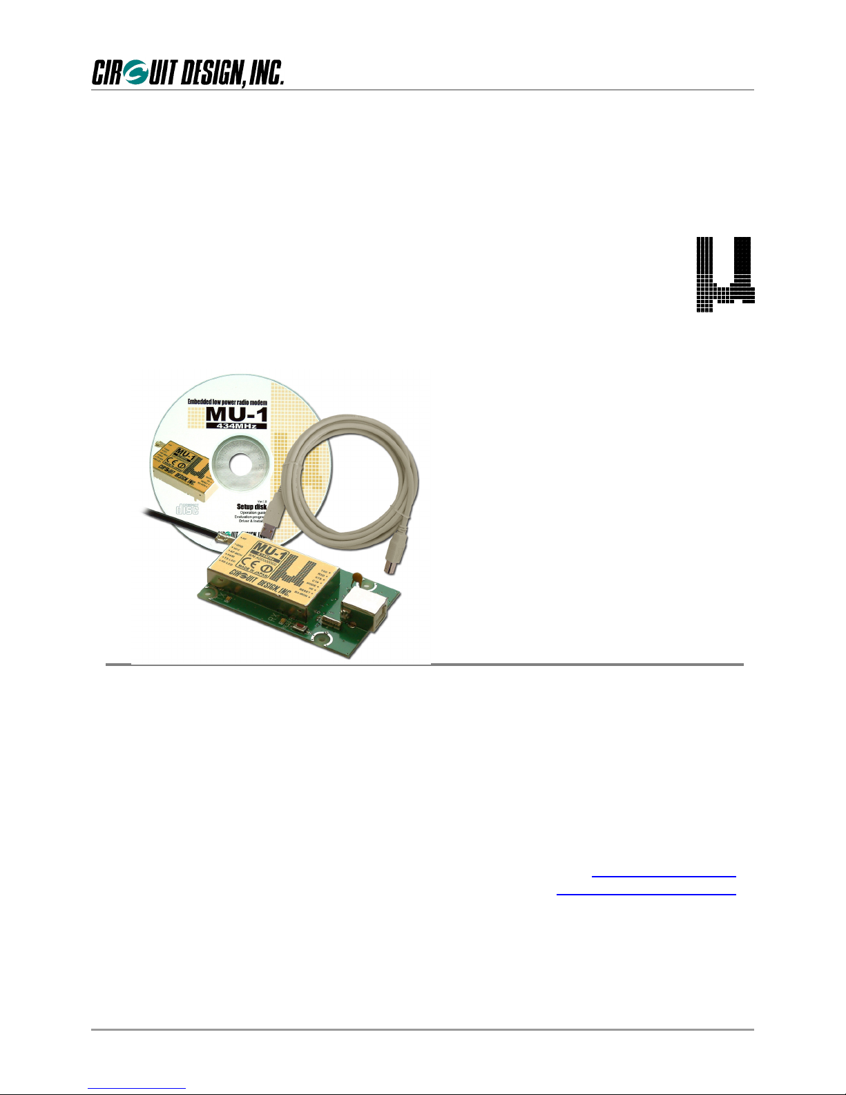
1. The “setup disk” is the CD-ROM that comes with each MU-1 series kit, that contains the setup program,
operation guide and so on.
2. The “evaluation program”is a program for evaluation of the MU-1 series of products, called the MU-1
Evaluation Software Program MU1-ESP. It is found inside the “Circuit Design” folder that appears on the
desktop of your PC after installation.
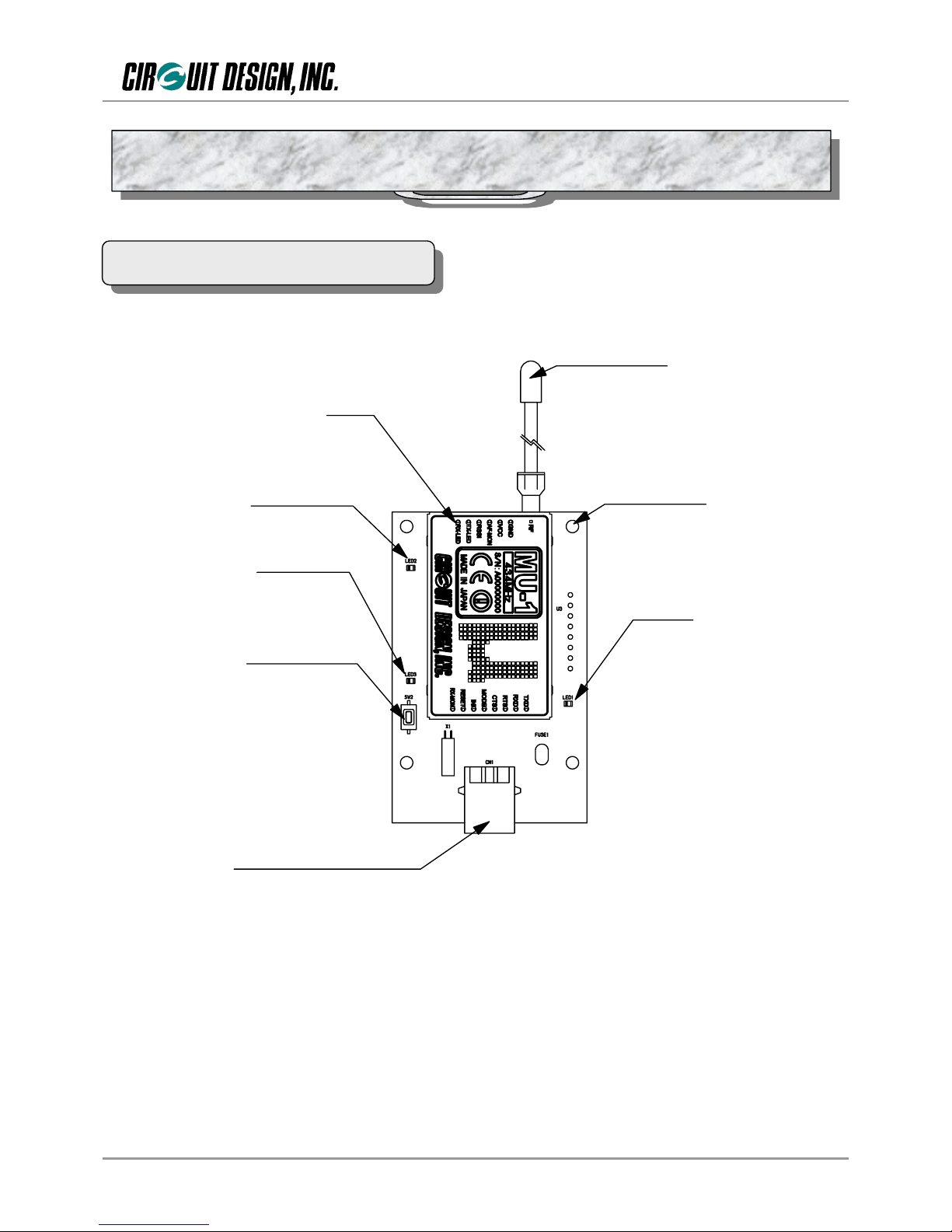
1.1.3 Features
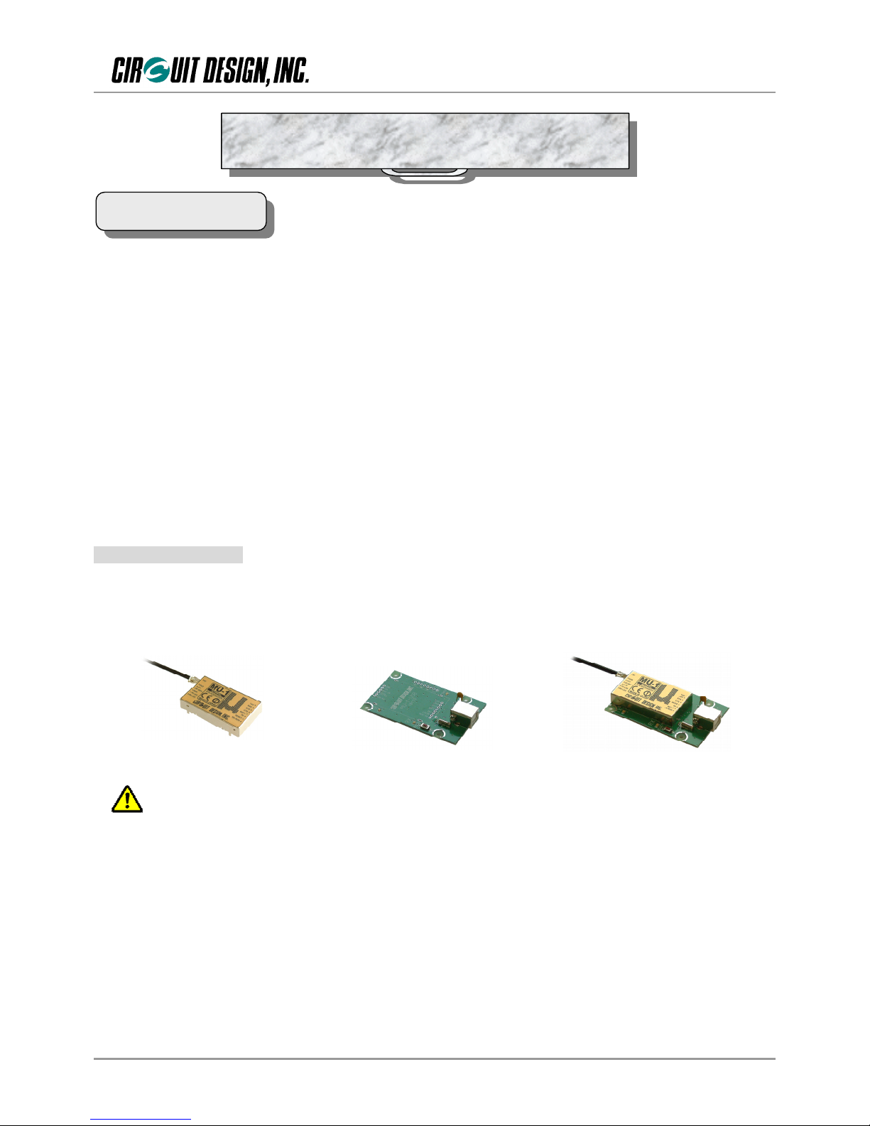
The kit uses the MU-1 that has obtained the CE mark.
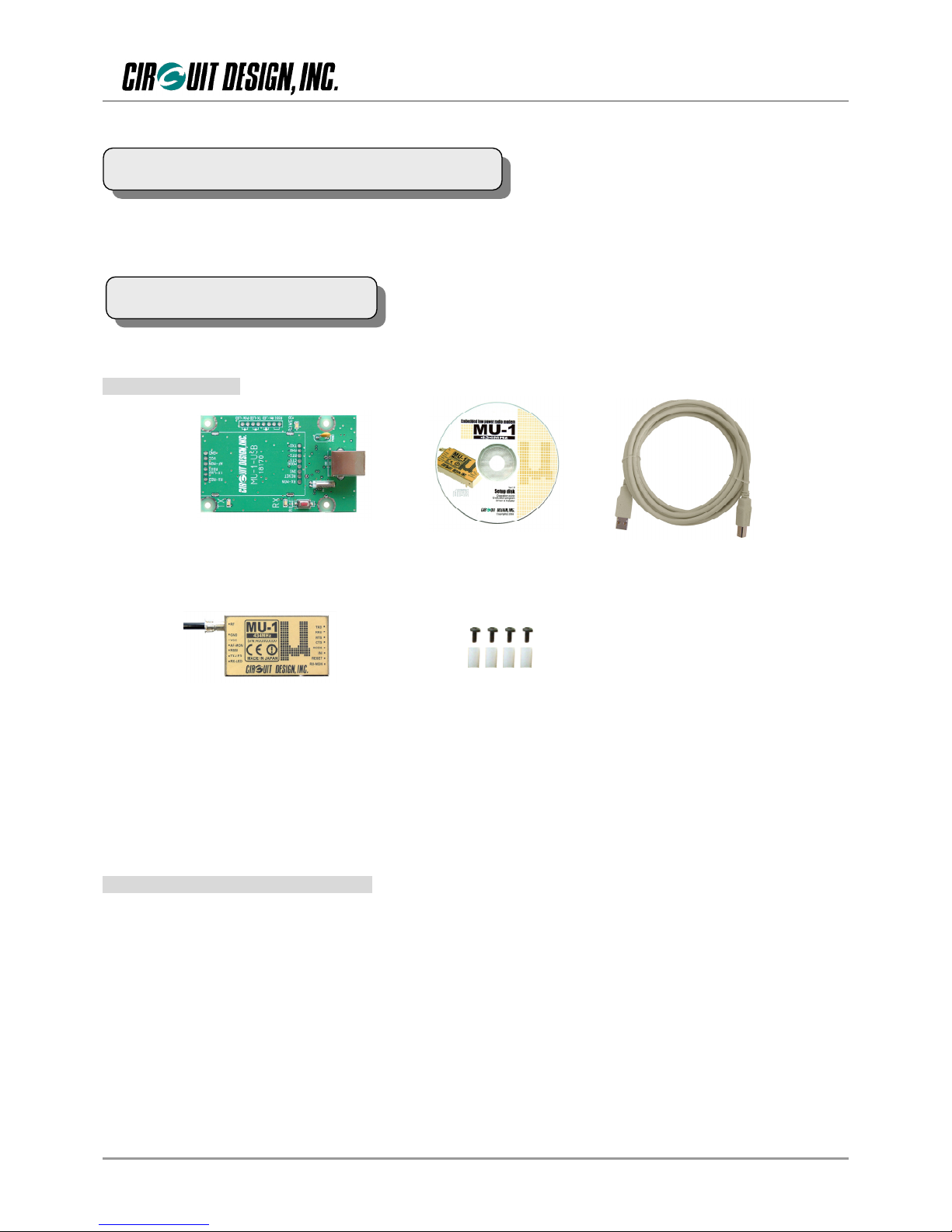
Power for the MU1-USB is supplied by the USB interface wire.
The COM port used is recognized as a VCP *1, and the user need only create a control program for accessing a
normal COM port.
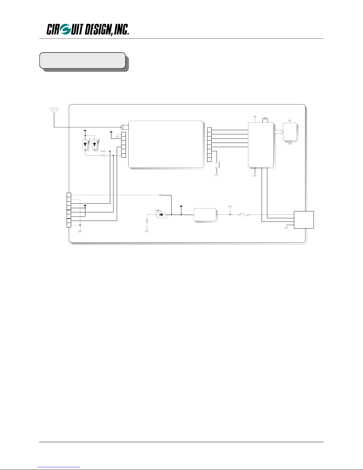
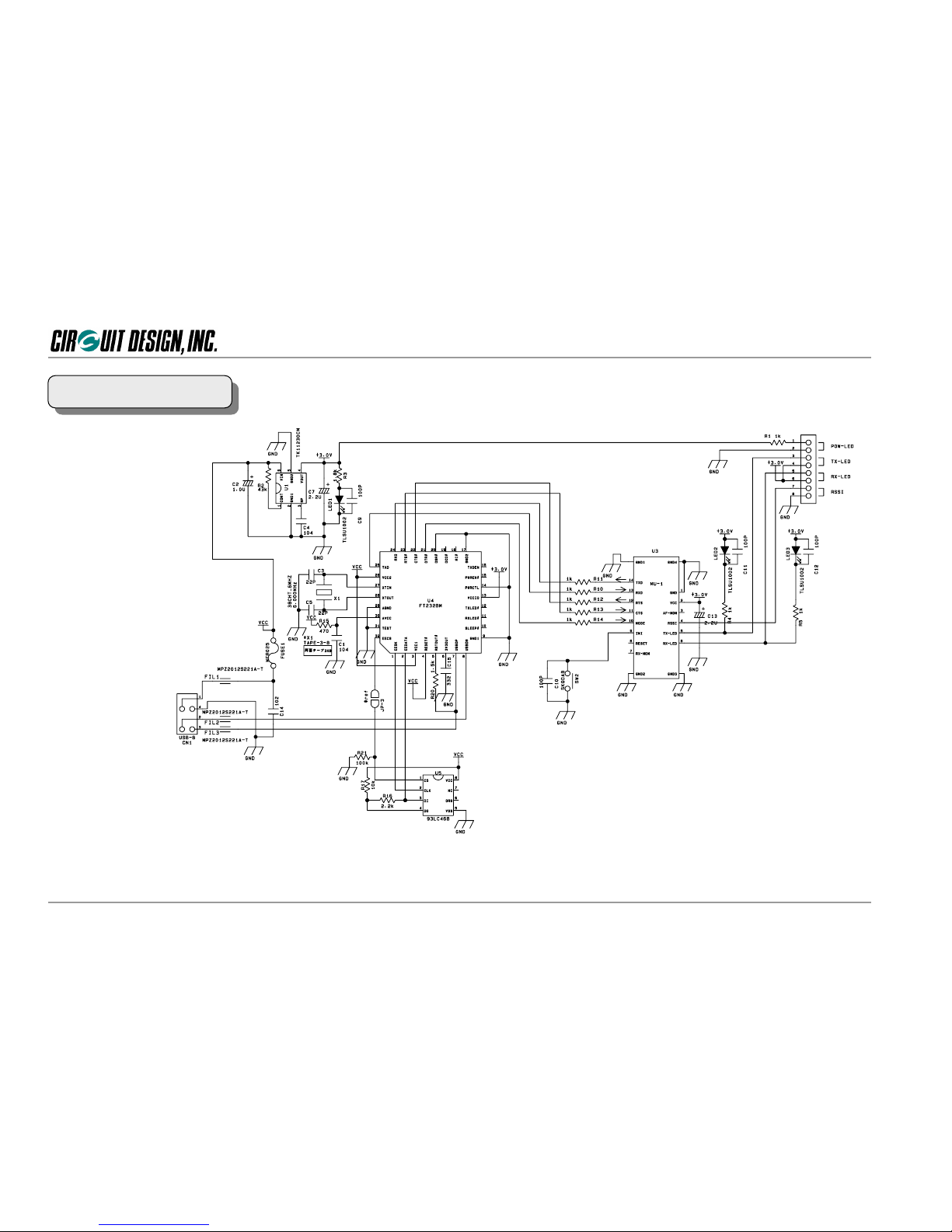
Circuit diagrams for making user systems are publicly available.
The product can be embedded in a case, and can be used for making products for radio control from a PC.
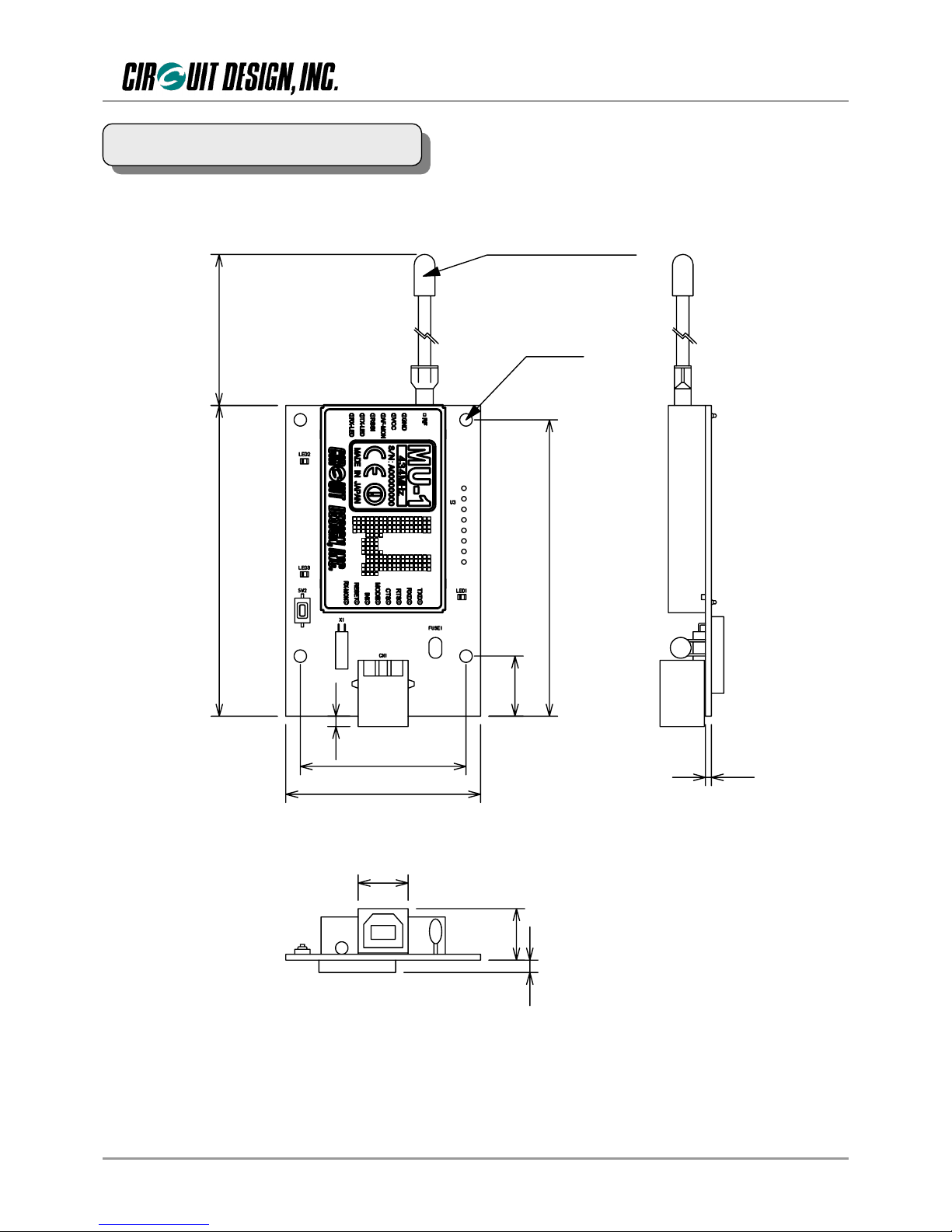
Compact size (47 mm × 78mm × 16 mm) fits in a small housing.
Features of the MU-1 evaluation program;
1. You can issue all commands for controlling the MU1-USB.
2. There is a test program for checking the communication performance of the MU1-USB.
3. There is an air monitor function for checking the status of radio waves in the field.
*1: Recognized as a VCP (virtual COM port) when the dedicated driver is installed.
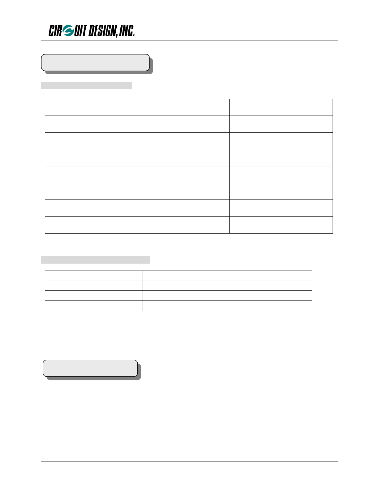
1.1.4 Applications
Serial data transmission
Energy monitoring, data monitoring devices, handy terminals, barcode readers
Telecontrol
Remote control for construction machinery, display devices, motor control, lifters
Remote control of FA equipment
Telemetry
Water level monitors for rivers and dams, temperature and humidity gauges, rain gauges, pressure gauges,
voltmeters, ampere meters
Systems used with MU1-UIK must meet the following conditions.
1. OS: Windows XP, Windows 2000, Windows Me, or Windows 98
2. Web browser: Internet Explorer 5.01 or higher
3. Hard disk capacity: 30 MB or more
4. Memory: 60 MB or more
1.2 System Requirements

OG_MU1-UIK_v20e 4 Circuit Design, Inc.
OPERATION GUIDE
Product name: MU-1 USB interface kit Part number: MU1-UIK
The contents of the kit are as follows. First, please check that you have all the items.
1.4.1 Accessories
MU1-USBIF x 1
MU-1 x 1 Spacer (10mm) x 4
Setup disk x 1 Shield cable (3m) x 1
Screw (M2.6 x 6mm) x 4
1.MU-1 1
2. MU-1 USB interface board MU1-USBIF 1
3. Double shield USB cable (3 m) 1 * USB Ver. 2.0 High speed cable
4. Spacers (used as legs) 10 mm 4
5. Screws for spacers M2.6 × 6 mm 4
6. Setup disk (CD-ROM) 1
7. Setup disk manual 1
1.4.2 Main contents of the setup disk
1. VCP (virtual COM port) driver
2. MU-1 Evaluation Program
3. MU-1 operation guide
4. MU1-ESP operation guide
1.3 Product Name and Part Number
1.4 Contents of the Kit

OG_MU1-UIK_v20e 5 Circuit Design, Inc.
OPERATION GUIDE
Rese t sw i tch
RX -LED
TX -LED
MU - 1
4 -moun t ing ho les
Powe r LED
USB -B t y p e r e c e p t a c l e
λ/4 lead an tenna
USB-B receptacle: For connecting the double shield USB cable (USB 2.0 High Speed).
Power LED: The LED comes on when the USB cable is connected.
λ/4 lead antenna: A λ/4 long lead antenna. (ANT-LEA-01)
MU-1: A low power radio modem.
TX-LED: On when data is transmitted.
RX-LED: On when data is received.
Initialize switch: Resets the MU-1 mounted on the MU1-USB to the factory default settings.
Initialize the unit if communication with the MU-1 is not possible or if you are uncertain of the internal settings.
2.1 Part Names and Functions
Chapter 2 The MU1-USB (MU-1 + MU1-USBIF)

OG_MU1-UIK_v20e 6 Circuit Design, Inc.
OPERATION GUIDE
MU-1
λ/4
Antenna
Regulator
+3v
13
12
11
10
9
8
14
7
4
5
6
3
2
1
INI
RXD
TXD
RTS
CTS
MODE
RESET
RX-MON
RF
GND
VCC
AF-MON
RSSI
TX-LED
RX-LED
Tx
LED
Rx
LED SW2
USB
Controller
EEPROM
VCC
1
2
3
4
5
6
7
8
+3v +3v
+3v +3v
Power
LED
Power LED
Tx LED
Rx LED
RSSI
GND
GND
+3v
+3v
Vbus 1
USB-B
Receptacle
D- 2
D+ 3
GND 4
2.2 Block Diagram

OG_MU1-UIK_v20e 7 Circuit Design, Inc.
OPERATION GUIDE
2.3.1 General specifications
Item Specification Unit Remarks
Supply voltage USB bus power
Consumption current Transmitting: 63 / Receiving: 50 mA USB bus power
Operating temperature -20 to +60 ºC The range varies with the temperature
conditions.
LED indicator Tx, Rx, Power
Switch Initialize
External dimensions 47 × 78 × 16 (W × D × H) mm Including the connector.
Not including the antenna.
Unit weight 47 g
2.3.2 USB interface specifications
Refer to the operation guide of the MU-1 mounted on the MU1-USB for the channel table. The frequency band is
shown on the label of the MU-1.
Item Specification
Interface specification USB Ver. 2.0 Full speed
Receptacle USB-B type receptacle
Adapter USB-B type plug
2.4 Channel Table
2.3 Main Specifications

OG_MU1-UIK_v20e 8 Circuit Design, Inc.
OPERATION GUIDE
75
71 .5
14 .5
4-Φ3 .0
40
47
12 .05
1.4
312 .4
2.5
183
1/4λ lead an tenna
2.5 External Dimensions

OG_MU1-UIK_v20e 9 Circuit Design, Inc.
OPERATION GUIDE
* When making your circuit board based on this circuit diagram, pay due attention to high frequency noise around the USB chip and from the interface.
1. Exercise caution in placement of the MU1 and USB chip. In addition, there are cases where shielding is necessary around the chip.
2. Add a noise filter to the USB interface signal wire.
3. Ensure a sufficiently large ground pattern for the MU-1. In addition, provide shielding for the signal wire too.
2.6 Circuit Diagram
Questo manuale è adatto per i seguenti modelli
2
Indice
Altri manuali CIRCUIT DESIGN Interfaccia USB
Manuali Interfaccia USB popolari di altre marche

PASCO
PASCO SCIENCEWORKSHOP 750 Manuale utente

Phonic
Phonic FIREFLY 302 USB Manuale utente

OHAUS
OHAUS Scout STX Series Manuale utente

Denon
Denon DN-HC4500 - DJ Mixer USB Controller Manuale utente

Lutron Electronics
Lutron Electronics Stanza SZ-CI-USB-CPN5138 Manuale utente

Paradox
Paradox PMC5-TI00 Manuale utente


