Cisco MERAKI MR46E Manuale utente

MR46E nstallation Guide
The Cisco Meraki MR46E are dual-band enterprise class 802.11ax cloud-managed access points. Designed for highest
capacity and highest density, the MR46E meets the needs of the most demanding environments. The access point also
includes a third radio dedicated to optimizing the RF environment and securing the airwaves.
About this Guide
This guide provides instruction on how to install and configure your MR46E access points. This guide also provides
mounting instructions and limited troubleshooting procedures. For more wireless installation guides, refer to the wireless
installation guides section on our documentation website.
Product Overview
Physical Specifications
MR46E
Interfaces
• 1x 100/1000/2.5G BASE-T Ethernet (RJ45)
• 1x DC power connector (5.5 mm x 2.5 mm, center positive)
Power
• Power over Ethernet: 42.5 - 57 V (802.3at compatible)
•Alternative: 12 V DC input
•Power consumption: 30W max (802.3at)
•Power over Ethernet injector and DC adapter sold separately
Note: Actual power consumption may vary depending on the AP
usage.
1
Environment
• Operating temperature: 32 °F to 104 °F (0 °C to 40 °C)
• Humidity: 5 to 95% non-condensing
Physical Security
• Two security screw options (included) (13.5 mm long and 2.5
mm diameter and 5 mm head)
• Kensington lock hard point
• Concealed mount plate with anti-tamper cable bay
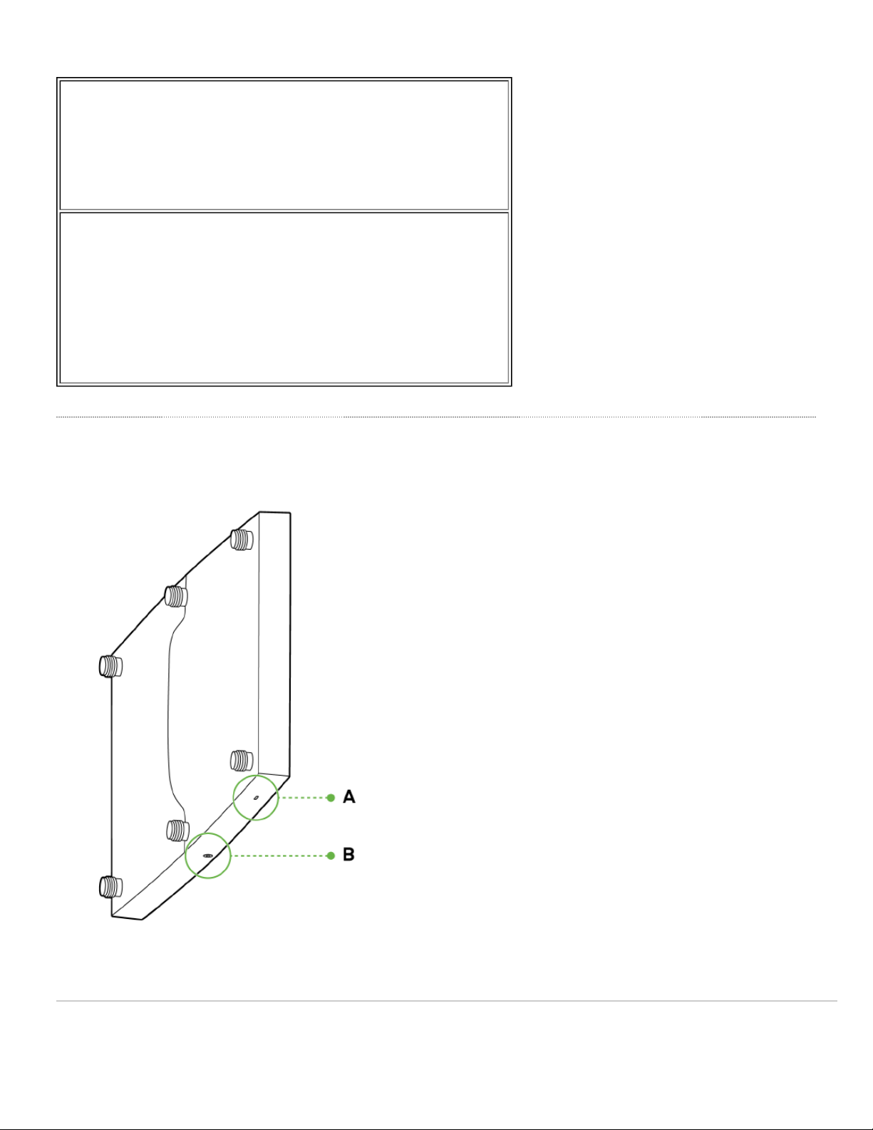
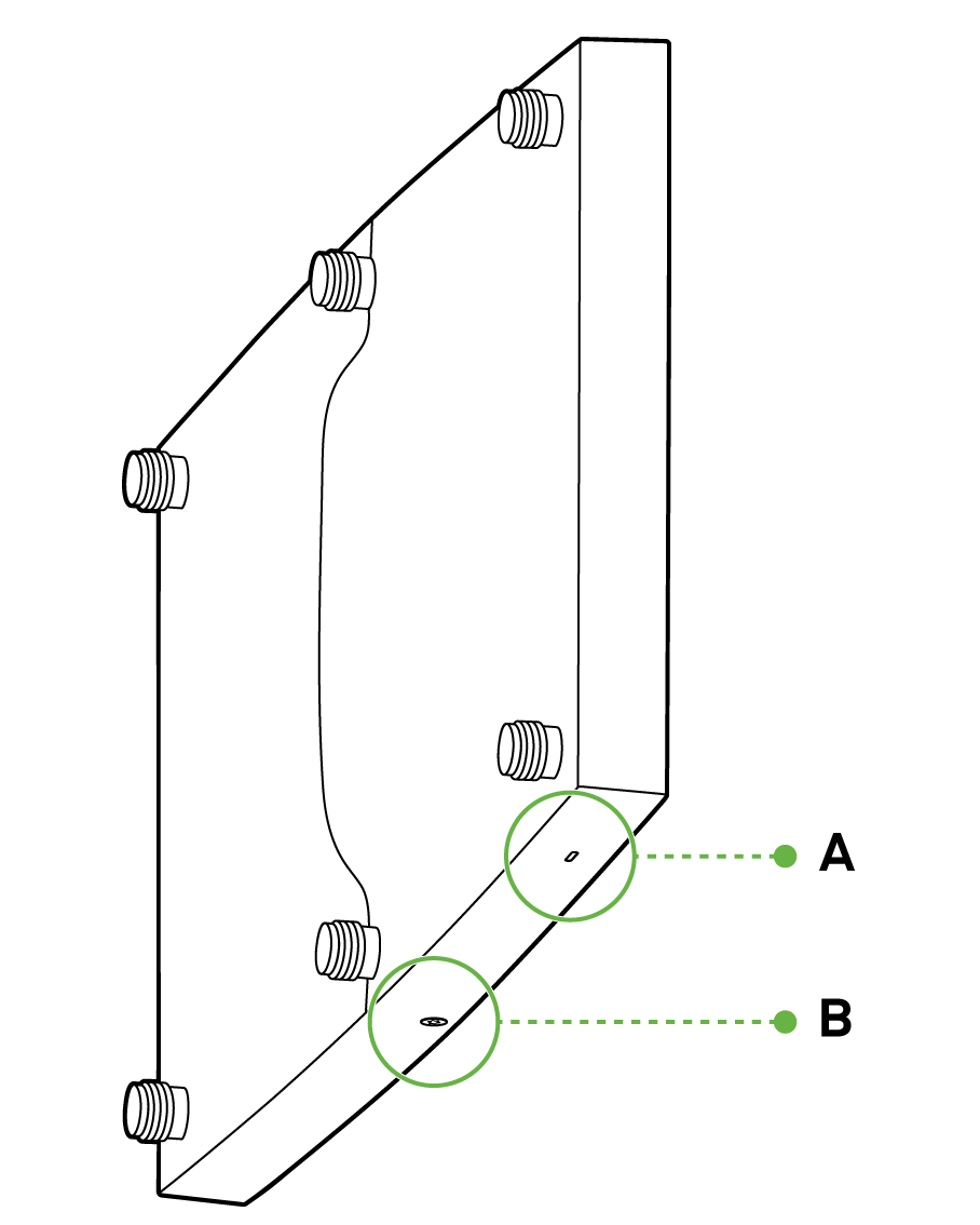
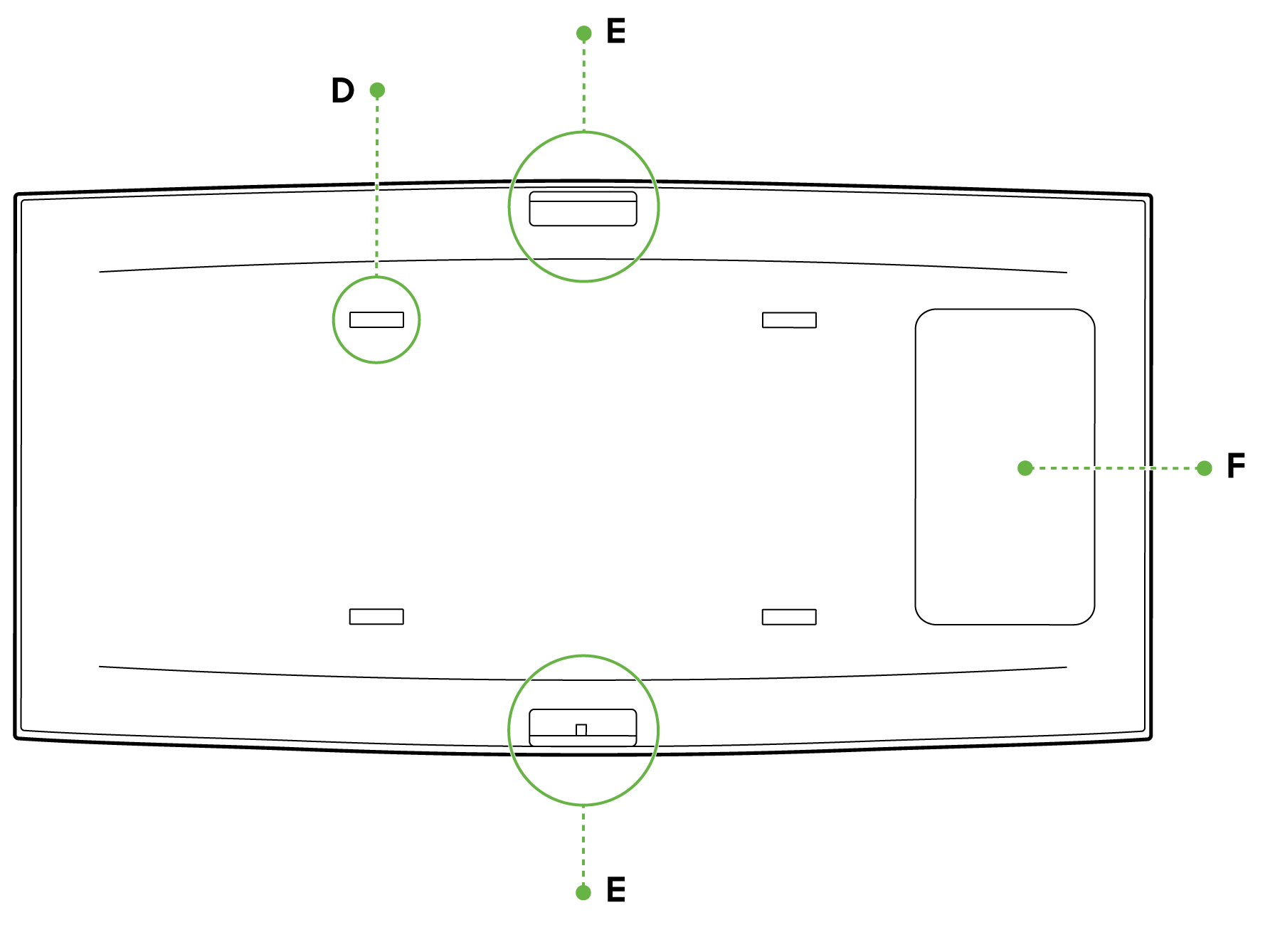
Product View and Physical Features
Your MR46E has the following features:
A - LED indicator
2
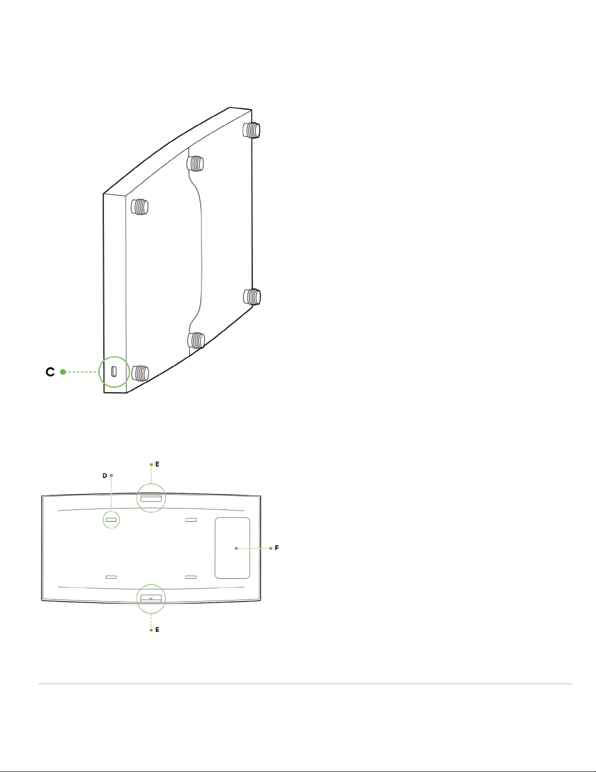

E - Mount cradle attachment point
F - Cable access bay
Security Features
The MR46E features multiple options for physically securing the access point after installation:
1. Security screw – The accessory kit includes screws that can be used to secure the access point to the mount
cradle. Engaging the security screw prevents accidental dislodging and theft.
2. Kensington lock – The access point contains a hard point that allows it to be secured to any nearby permanent
structure using a standard Kensington lock.
External Antenna Ports
The MR46E has 6 external antenna ports
Ethernet Ports
The MR46E features a Gigabit Ethernet RJ45 port that accepts 802.3at power (labeled “Eth0, PoE”). This port should be
4

used for uplink to your WAN connection.
The port labeled “PoE” accepts 802.3at power and should be used as the primary uplink to your LAN/WAN.
Power Source Options
The MR46E access point can be powered using either the Meraki AC Adapter, PoE njector (both sold separately), or a
third-party PoE switch.
Factory Reset Button
f the button is pressed and held for at least five seconds and then released, the AP will reboot and be restored to its
original factory settings by deleting all configuration information stored on the unit.
LED Indicators and Run Dark Mode
Your access point is equipped with a multi-color LED light on the front of the unit to convey information about system
functionality and performance:
• Orange - AP is booting (permanent Orange suggests hardware issue)
• Rainbow - AP is initializing/scanning
• Blinking Blue - AP is upgrading
• Green - AP in Gateway mode with no clients
• Blue - AP in Gateway mode with clients
• Blinking Orange - AP can't find uplink
NOTE: Blinking Green LED indicates that the device is in site survey mode. Please see the Conducting Site Surveys
with MR Access Points for more details.
The MR46E access point may be operated in “Run Dark” mode for additional security and to reduce the visibility of the
access point. n this mode, the LED will not be illuminated. This mode may be enabled through Meraki Dashboard.
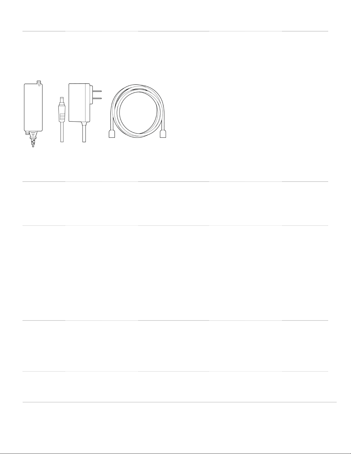
Package Contents
The access point packages contain the following:
5

MR46E Cloud-Managed Access Point
Mount cradle including built-in level tool
Drop ceiling mount kit
6

Wall screws, wall screw anchors, and security screws
Safety and Warnings
These operations are to be taken with respect to all local laws. Please take the following into consideration for safe
operation:
• Power off the unit before you begin. Read the installation instructions before connecting the system to the power
source.
• Before you work on any equipment, be aware of the hazards involved with electrical circuitry and be familiar with
standard practices for preventing accidents.
• Read the wall-mounting instructions carefully before beginning installation. Failure to use the correct hardware or to
follow the correct procedures could result in a hazardous situation to people and damage to the system.
• This product relies on the building’s installation for short-circuit (overcurrent) protection. Ensure that the protective
device is rated not greater than: 15 A, 125 Vac, or 10A, 240 Vac.
• Please only power the device with the provided power cables or standard PoE to ensure regulatory compliance.
7

Pre-install Preparation
You should complete the following steps before going on-site to perform an installation.
Configure your Dashboard Network
The following is a brief overview only of the steps required to add an access point to your network. For detailed
instructions about creating, configuring and managing Meraki wireless networks, refer to the online documentation
(documentation.meraki.com).
1. Login to http://dashboard.meraki.com. f this is your first time, create a new account.
2. Find the network to which you plan to add your APs or create a new network.
3. Add your APs to your network. You will need your Meraki order number (found on your invoice) or the serial
number of each AP, which looks like Qxxx-xxxx-xxxx, and is found on the bottom of the unit. You will also need
your Enterprise license key, which you should have received via email.
4. Go to the map / floor plan view and place each AP on the map by clicking and dragging it to the location where you
plan to mount it.
Check and Set Firmware
To ensure your access point performs optimally immediately following installation, it is recommended that you facilitate a
firmware upgrade prior to mounting your AP.
1. Attach your AP to power and a wired nternet connection. See the "Power the Ap" section for details.
2. The AP will turn on and the LED will glow solid orange. f the unit does not require a firmware upgrade, the LED
will turn either green (no clients associated) or blue (clients associated) within thirty seconds.
* f the unit requires an upgrade, the LED will begin blinking orange until the upgrade is complete, at which point the LED
will turn solid green or blue. You should allow at least a few minutes for the firmware upgrade to complete, depending on
the speed of your internet connection.
Check and Configure Upstream Firewall Settings
f a firewall is in place, it must allow outgoing connections on particular ports to particular P addresses. The most
current list of outbound ports and P addresses for your particular organization can be found on the firewall configuration
page in your dashboard.
Assigning an P Address
All gateway A (An AP with Ethernet connections to the LAN) must be assigned routable P addresses. These P
addresses can be dynamically assigned via DHCP or statically assigned.
8

Dynamic Assignment
• When using DHCP, the DHCP server should be configured to assign a static P address for each MAC address
belonging to a Meraki AP. Other features of the wireless network, such as 802.1X authentication, may rely on the
property that the APs have static P addresses.
Static Assignment
• Static Ps are assigned using the local web server on each AP. The following procedure describes how to set the
static P:
• Using a client machine (e.g., a laptop), connect to the AP wirelessly (by associating to any SS D broadcast by the
AP) or over a wired connection.
• f using a wired connection, connect the client machine to the AP either through a PoE switch or a PoE njector. f
using a PoE switch, plug an Ethernet cable into the AP’s Ethernet jack, and the other end into a PoE switch. Then
connect the client machine over Ethernet cable to the PoE switch. f using a PoE njector, connect the AP to the
“PoE” port of the njector, and the client machine to the “LAN” port.
• Using a web browser on the client machine, access the AP’s built-in web server by browsing
to http://my.meraki.com. Alternatively, browse to http://10.128.128.128.
• Click on the “Uplink Configuration” tab. Log in. The default login is the serial number (e.g. Qxxx-xxxx-xxxx), with no
password (e.g., Q2DD-551C-ZYW3).
• Configure the static P address, net mask, gateway P address and DNS servers that this AP will use on its wired
connection.
• f necessary, reconnect the AP to the LAN.
Static IP via DHCP Reservations
• nstead of associating to each Meraki AP individually to configure static P addresses, an administrator can assign
static P addresses on the upstream DHCP server. Through “DHCP reservations,” P addresses are “reserved” for
the MAC addresses of the Meraki APs. Please consult the documentation for the DHCP server to configure DHCP
reservations.
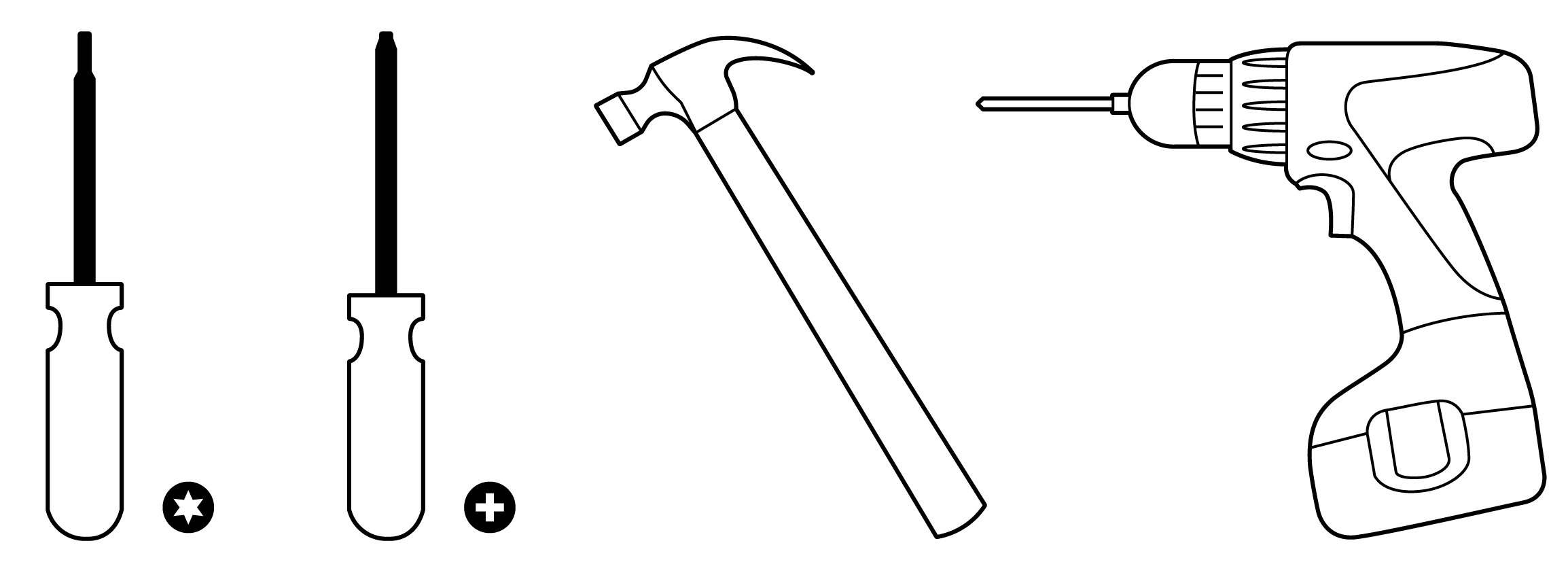
Collect Tools
You will need the following tools to perform an installation:
T8 Torx Screwdriver, Phillips screwdriver, Hammer, Drill with 1/4" (6.3mm) bits
9
Collect Additional Hardware for nstallation
You will need the following hardware to perform an installation:
802.3at PoE Power Source (either PoE switch or Meraki 802.3at PoE Injector) or an AC adaptor and network cables
with RJ45 connectors long enough for your particular mounting location
nstallation nstructions
Warning: Due to the heat dissipation in the back of APs during normal operation, please do not stack powered on APs
on top of each other during pre-installation to avoid heat damage.
Choose Your Mounting Location
A good mounting location is important to getting the best performance out of your access point. Keep the following in
mind:
1. The device should have unobstructed line of sight to most coverage areas. For example, if installing in an office
filled with workspaces divided by mid-height cubicle walls, installing on the ceiling or high on a wall would be ideal.
2. Power over Ethernet supports a maximum cable length of 300 ft (100 m).
3. f being used in a mesh deployment, the AP should have line of sight to at least two other Meraki devices. A Cisco
Partner can help ensure that your AP placement is ideal.
nstall the AP
For most mounting scenarios, the access point mount cradle provides a quick, simple, and flexible means of mounting
your device. The installation should be done in two steps. First, install the mount cradle to your selected location. Then,
attach the AP to the mount cradle.
Attach the Mount Cradle
The access point mount cradle can be used to install your access point in a wide range of scenarios: wall or solid ceiling,
10
Indice
Altri manuali Cisco MERAKI Punto di accesso wireless

Cisco MERAKI
Cisco MERAKI MX95 Series Manuale

Cisco MERAKI
Cisco MERAKI MR57 Manuale utente

Cisco MERAKI
Cisco MERAKI MR42 Manuale utente

Cisco MERAKI
Cisco MERAKI MR36H Manuale utente

Cisco MERAKI
Cisco MERAKI MR44-HW Manuale utente

Cisco MERAKI
Cisco MERAKI MR44 Manuale utente

Cisco MERAKI
Cisco MERAKI MR30H Manuale utente

Cisco MERAKI
Cisco MERAKI MR46 Manuale utente

Cisco MERAKI
Cisco MERAKI MR36 Manuale utente

Cisco MERAKI
Cisco MERAKI Catalyst CW9164 Manuale utente


 Manuale utente")
