Clear One VIEW Pro - E120 Manuale utente

VIEW®Pro - E120 Digital AV Encoder
InstallatIon and User ManUal
AVoIP™

ClearOne
5225 Wiley Post Way
Suite 500
Salt Lake City, UT 84116
Telephone 1.800.283.5936
1.801.974.3760
FAX 1.801.303.5711
E-mail [email protected]
On the Web www.clearone.com
VIEW Pro E120 InstallatIon Manual
ClEaronE DoCuMEnt
DOC-0149-001- October, 2014 (Rev. 1.0)
© 2014 ClearOne All rights reserved. No part of this document
may be reproduced in any form or by any means without written
permission from ClearOne. ClearOne reserves specific privileges.
Information in this document is subject to change without notice.

INTRODUCTION
Product Overview.................................................................................................................................................... 1
StreamNet AVoIP™ Video Platform ...................................................................................................................................1
Device Application.............................................................................................................................................................1
Included with Your VIEW Pro Encoder...............................................................................................................................1
CONNECTIONS
Inputs and Connections.......................................................................................................................................... 2
Status LED.........................................................................................................................................................................2
10/100/1000 Ethernet Jack ...............................................................................................................................................2
HDMI Inputs.......................................................................................................................................................................3
IR In....................................................................................................................................................................................3
IR Out ................................................................................................................................................................................3
RS-232 (COM)...................................................................................................................................................................3
19VDC Input ......................................................................................................................................................................3
INSTALLATION
Physical Characteristics ......................................................................................................................................... 4
Dimensions (Excluding Connectors).................................................................................................................................4
Mounting the E120 .................................................................................................................................................. 4
The E120 in a Network ............................................................................................................................................ 6
Connecting the E120............................................................................................................................................... 6
SOFTWARE SETUP OF THE E120
LUA File ................................................................................................................................................................... 7
E120 Screens in the Dealers Setup Program ........................................................................................................ 8
Adding an E120 to a Project .............................................................................................................................................8
The Information Tab.........................................................................................................................................................10
The Sources Tab..............................................................................................................................................................11
The Sources Tab Advanced Configuration......................................................................................................................12
Editing a Stream.........................................................................................................................................................13
Premium Features ......................................................................................................................................................15
Editing Stream Presets...............................................................................................................................................15
Video Presets ......................................................................................................................................................16
Audio Presets......................................................................................................................................................18
The GPIO Settings Tab ....................................................................................................................................................20
Input Macro Assignments ..........................................................................................................................................20
Relay Assignments.....................................................................................................................................................20
Table of Contents

VIEW PRO RS-232 CONTROL
LUA File Driver Templates..................................................................................................................................... 21
Preparing the New One-Way RS-232 Driver File ................................................................................................. 21
Preparing the Encoder/Decoder .......................................................................................................................... 23
Modifying the One-Way Driver File....................................................................................................................... 24
VIEW PRO AND VIEW LEGACY INTEROPERABILITY
Control Sharing..................................................................................................................................................... 29
Audio Streaming Interoperability ......................................................................................................................... 29
IR Learning and Control ....................................................................................................................................... 30
Firmware Upgrading ............................................................................................................................................. 30
VIEW PRO ACCESSORY KITS
Kit Descriptions..................................................................................................................................................... 31
COMPLIANCE
Compliance Overview........................................................................................................................................... 32
RoHS Compliance...........................................................................................................................................................32
Stainability .......................................................................................................................................................................32
Electrical Safety Advisory..................................................................................................................................... 32
Compliance Details............................................................................................................................................... 32
FCC Compliance.............................................................................................................................................................32
European Compliance ....................................................................................................................................................32
SERVICE AND SUPPORT
Technical Support ................................................................................................................................................. 33
Sales ...................................................................................................................................................................... 33
Techsales............................................................................................................................................................... 33
Product Returns .................................................................................................................................................... 33

InstallatIon Manual 1
Introduction
PRODUCT OVERVIEW
streamnet aVoIP™ VIDEo PlatforM
The StreamNet IP platform is designed to send high-quality audio and video over a TCP/IP network
(AVoIP™). An encoder, such as a VIEW Pro E120, takes digital video and audio from a source
device, such as a receiver, cable box or DVR, and makes the source available anywhere on the
StreamNet network. A decoder, such as the VIEW Pro D110, takes the combined video and audio
stream and decodes it. The D110 then sends the video and audio to a display such as a HDTV or
projector and sound system.
DEVICE aPPlICatIon
The E120 is a high definition, Internet Protocol, compressed multimedia encoder. The E120
connects to a TCP/IP network using an Ethernet connection. The E120, installed at the location of
the multimedia source, works in connection with the D110 decoder, installed at the location of the
display.
Installation should be done by a qualified Dealer Service representative. Please consult the DigiLinX
Installation Manual for device use in system configuration.
InCluDED WIth Your VIEW Pro EnCoDEr
The following items are included with the VIEW Pro Encoder:
Item Description
910-0000-001 VIEW Pro Encoder E120
Power Supply, Power Cord
910-0002-001 VIEW Pro Rack Mount
• 2X - Rack Ear, Extended length
• 6X - Screw, M3 x 6mm, Pan-head, Philips, Thread Locking, Black
QSG-0010-001 VIEW PRO Encoder/Decoder Quick Start Guide

2 tEChnICal suPPort: 800.283.5936
Connections
The VIEW Pro E120 Encoder has the following input and output connectors on the back of the unit.
• 1x - IR Input connector compatible with SteamNet IR sensor (3.5mm)
• 1x - IR Input Receiver window on front panel
• 1x - IR Output connector compatible with SteamNet IR emitter (3.5mm)
• 2x - Balanced Audio Input (Two Modular Phoenix-type connectors, left and right)
• 3x - GPIO (General Purpose Inputs - Digital, 0/5V, Phoenix-type)
• 3x - GPIO (General Purpose Outputs - Latching, Relays, Phoenix-type)
• 1x - Stereo 3.5mm Barrel Plug (Line Level) Input
• 1x - Stereo 3.5mm Barrel Plug (Line Level) Output (Currently not used)
• 2x - HDMI-input connectors.
• 2X - RS-232 DB-9 connector
• 2x - RJ45 10/100/1000 Mb Ethernet jack (Use only jack 1)
• 3x - USB connectors (one USB connector on front panel not visible)
• 1x - 19V DC Power Connector
INPUTS AND CONNECTIONS
The E120 transmits the digital video and audio on the network.
status lED
An LED on the front panel lights up when the unit is powered and to report status:
• Off=Off
• Yellow=Update process has started (e.g.: Update Devices)
• Blue=Normal Operation
• Green=System Startup/shutdown
• Red=Error Condition
10/100/1000 EthErnEt JaCks
The 10/100/1000 Mb Ethernet connector allows connection to TCP/IP networks setup to run
StreamNet. Only Port 1 (Red Jack) is supported. The other is a service port that MUST NOT be
connected.
InstallatIon Manual 3
hDMI InPuts
The HDMI connectors on the E120 receive digital video and audio.
Ir In
This jack allows connection of an StreamNet compatible infrared receiver. The infrared receiver can
pick up IR remote control signals for IR learning.
Ir out
This jack allows connection of an infrared transmitter. The infrared transmitter can send IR remote
control signals.
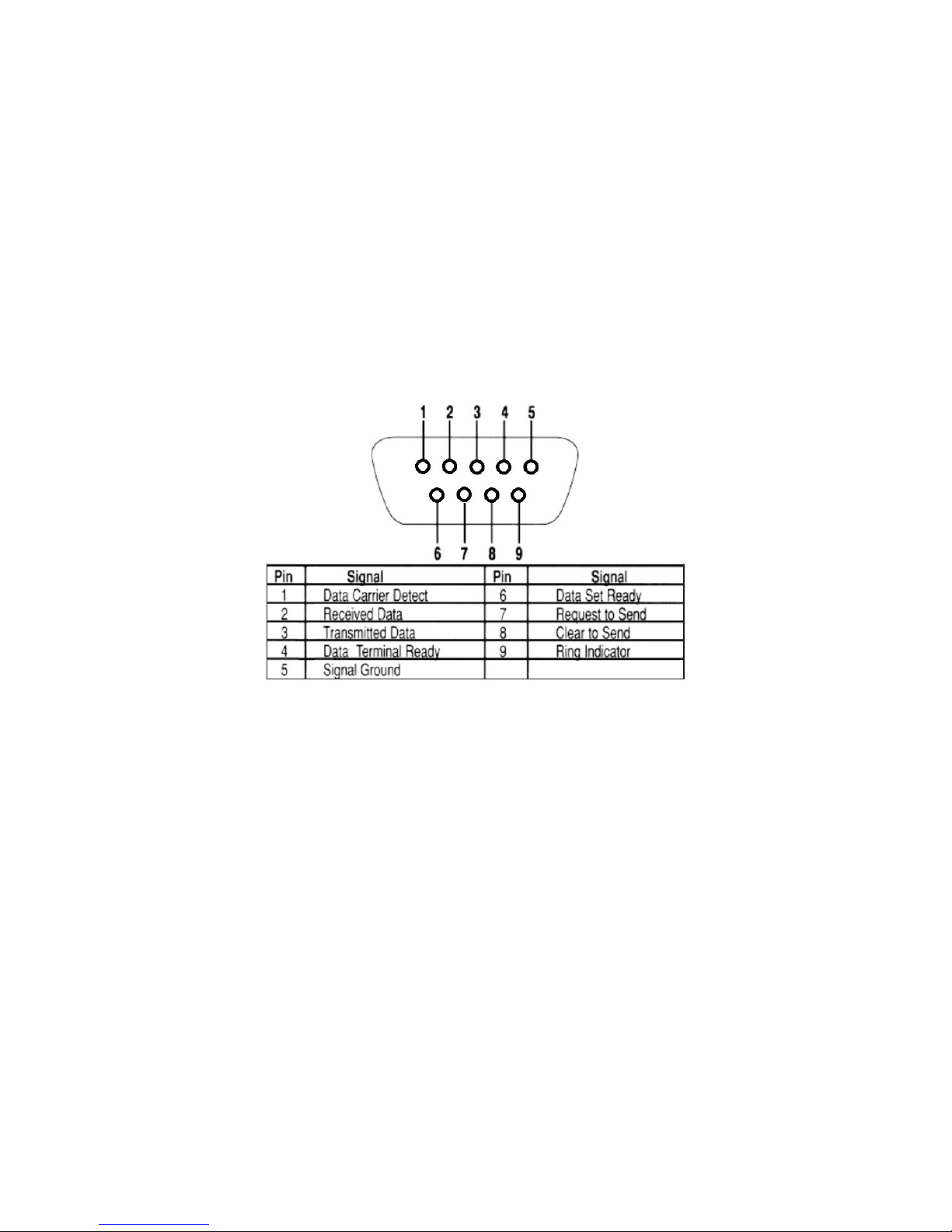
rs-232 (CoM)
These jacks allow the E120 to control a source, or other connected source device. They support
sending and receiving RS-232 commands to control devices.
19VDC InPut
This connector provides power input for the E120. This power is available using the included power
supply.

4 tEChnICal suPPort: 800.283.5936
Installation
PHYSICAL CHARACTERISTICS
DIMEnsIons (ExCluDIng ConnECtors)
Width: 12.2 inches (310mm)
Length: 7.4 inches (188mm)
Height: 1.75 inch (44.4mm)
MOUNTING THE E120
The VIEW Pro encoder includes a Rack Mount Kit (910-0002-001) with rack-mount ears that attach
to the encoder to facilitate mounting in a standard rack.
When mounted, the I/O connections are accessible from the back of the unit. (If needed, the unit
can also mount with the I/O connections facing the front of the rack.)
Surface Mounting
Rack Mounting
The VIEW Pro encoder can also be surface mounted using the optional Wall Mount Kit (910-0002-
002) with surface-mount ears that attach to the encoder to facilitate mounting.
An optional VESA mount bracket Kit (910-0002-006) is available for applications where an encoder
must be located on a VESA mount.
VESA Bracket
Wall Bracket
(Mount to stud or
other solid surface)
Unit with VESA Bracket
hangs on Wall Bracket
Surface Mounting
Rack Mounting

InstallatIon Manual 5
The metal cover snaps onto
the wall-mounted brackets
Edge protectors prevent
cover from making contact with the cables.
Use included wire ties to secure
the cables to the wall bracket
Make 11 inch spacing between
top and bottom bracket mounting holes
Mount the wall brackets
to a solid surface.
(Wall screws not included)
Two sections or more kits may be combined to make a longer raceway. Join them using the included spring pins.
The metal cover may be cut to size as needed.
There may some situations where the VIEW Pro cables cannot be concealed within a cabinet or in a
wall. These cables can be surface mounted and concealed using the optional 910-0002-003 VIEW
Pro Cable Raceway Kit. This raceway, in 12-inch joinable lengths, can be mounted to the wall to
secure and cover the cables to the VIEW Pro devices.

6 tEChnICal suPPort: 800.283.5936
THE E120 IN A NETWORK
The VIEW Pro E120 encoder takes digital video and audio from source devices such as media/disc
players, cable/satellite boxes, DVRs, and cameras, and then makes the digital video and audio
available anywhere on the StreamNet® IP network. a StreamNet TCP/IP network using a standard
10/100/1000 Mbit Ethernet connection. The VIEW Pro decoders, as counterparts, are installed at
the locations of the target video displays. They operate together: the encoders providing the IP
data for the decoders to deliver to the displays..
CONNECTING THE E120
The E120 Encoder connections are from the back of the unit as shown in the following diagram.
Left/Right
Balanced
Inputs
COM2 Port for
Source/3rd-Party
Device Control
COM1 Port for
Source/3rd-Party
Device Control
6 GPIO Ports
for Control
3 Inputs and
3 Outputs
3.5mm IR Input
IR Learning
3.5mm IR
Output for
Source Display
or 3rd-Party
Control
Network Port2
(Currently Not Used)
Network Port1 3.5mm Audio
Output for Line-level
Audio or Digital
Audio Output
3.5mm Line-level
Audio Input
2 x USB
3.0 Ports
for USB
Audio/Video
Devices
19 VDC
Input from
Power
Adapter
Power
On/Off
2 HDMI
Audio/Video Port
DSP forced
air intake
(Currently Not Used)
Indice
Altri manuali Clear One Convertitore multimediale

Clear One
Clear One VIEW Pro D210 Manuale utente

Clear One
Clear One VIEW Pro Manuale utente

Clear One
Clear One VIEW Lite DJ100 Manuale utente

Clear One
Clear One CONNECT CobraNet Manuale utente

Clear One
Clear One VIEW Lite EJ100 Manuale utente

Clear One
Clear One VIEW Pro D110 Manuale utente

Clear One
Clear One StreamNet AVoIP VIEW Pro Manuale utente

Clear One
Clear One ViewLinX VL9300 Manuale utente

Clear One
Clear One VIEW Pro D310 Manuale utente


