Clearfield FieldShield D-ROP Manuale utente

FieldShield D-ROP
Installation Manual ______________________________________________________
Manual 018958 REV C - Oct 2017

Direct: 763.476.6866 • National: 800.422.2537 • www.SeeCleareld.com • [email protected]
2
FieldShield D-ROP
Installation Manual _________________________________________________________
Manual 018958 REV C - Oct 2017
Table of Contents
Application 3
Description 3
Accessories 3
Technical Specications 4
Packaging 5
Required Tools 5
Installing into YOURx-Terminal 6
Installing into YOURx-TAP 8
Reducing Duct Length 9
Connector Cleaning Procedure 12
Drop Cable Options 15
Standard Warranty 16
Proprietary Notice 17
Technical Support 17
3
FieldShield D-ROP
__________________________________________________________ Installation Manual
Direct: 763.476.6866 • National: 800.422.2537 • www.SeeCleareld.com • [email protected]
Manual 018958 REV C - Oct 2017
Application
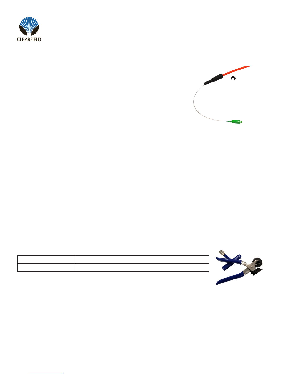
Building upon the restoration promise of FieldShield Pushable Fiber,
FieldShield D-ROP is a preconnectorized drop cable delivered to market
pre-placed in a 7mm microduct. The FlexConnector snaps into the FlexPort
providing an air-tight, water-tight connection between the YOURx-TAP and
YOURx-Terminal. Installed by the contractor as a single-pass deployment,
FieldShield D-ROP also provides ease of restoration. In the event of a future
ber cut, a eld technician easily identies the cut area, and utilizes a simple
coupler and a FieldShield Fiber Assembly to restore service.
Description
D-ROP cable presents the same footprint as a at drop cable with the added advantage of being restorable. Just like
traditional FieldShield microduct and ber, ber cuts are located, repaired and a new ber assembly is pulled from point
A to B with a pre-terminated LC assembly. In the event that an LC is not used, blunt ber is pulled and completed with a
fuse-on connector minimizing costs and time to restore the service outage. The FlexConnector is plugged directly into the
FieldShield YOURx-Terminal or YOURx-TAP FlexPort, providing a completely protected pathway from the access point
directly to the premise, business or antenna with the option for restoration after accidental ber cut. D-ROP does not have
the slack storage challenges that a at drop presents because the duct slack can be peeled or removed leaving only the
900um pre-terminated/tested ber assembly.
Part Number Description
FS-DUCT-OPENER Microduct Opener, D-ROP
Accessories

Direct: 763.476.6866 • National: 800.422.2537 • www.SeeCleareld.com • [email protected]
4
FieldShield D-ROP
Installation Manual _________________________________________________________
Manual 018958 REV C - Oct 2017
FieldShield D-ROP
Length Up to 2000 foot spool (-0/+5%)
Outside Diameter 0.276” (7mm)
Inside Diameter 0.138” (3.5mm)
Wall Thickness 0.069” (1.75mm)
Ovality ≤ 5%
Material HDPE
Installed Fiber 900 μm singlemode bend insensitive ber
Connector Style SC or LC
Operating Temperature -40°F to 176°F (-40°C to 80°C)
Color Orange or Black
Tone Wire Copper
Markings Part number, lot number, footage markers every two feet
Breakout Length 12 Inches
Min. Bend Radius 4.75” (120)
Technical Specications
5
FieldShield D-ROP
__________________________________________________________ Installation Manual
Direct: 763.476.6866 • National: 800.422.2537 • www.SeeCleareld.com • [email protected]
Manual 018958 REV C - Oct 2017
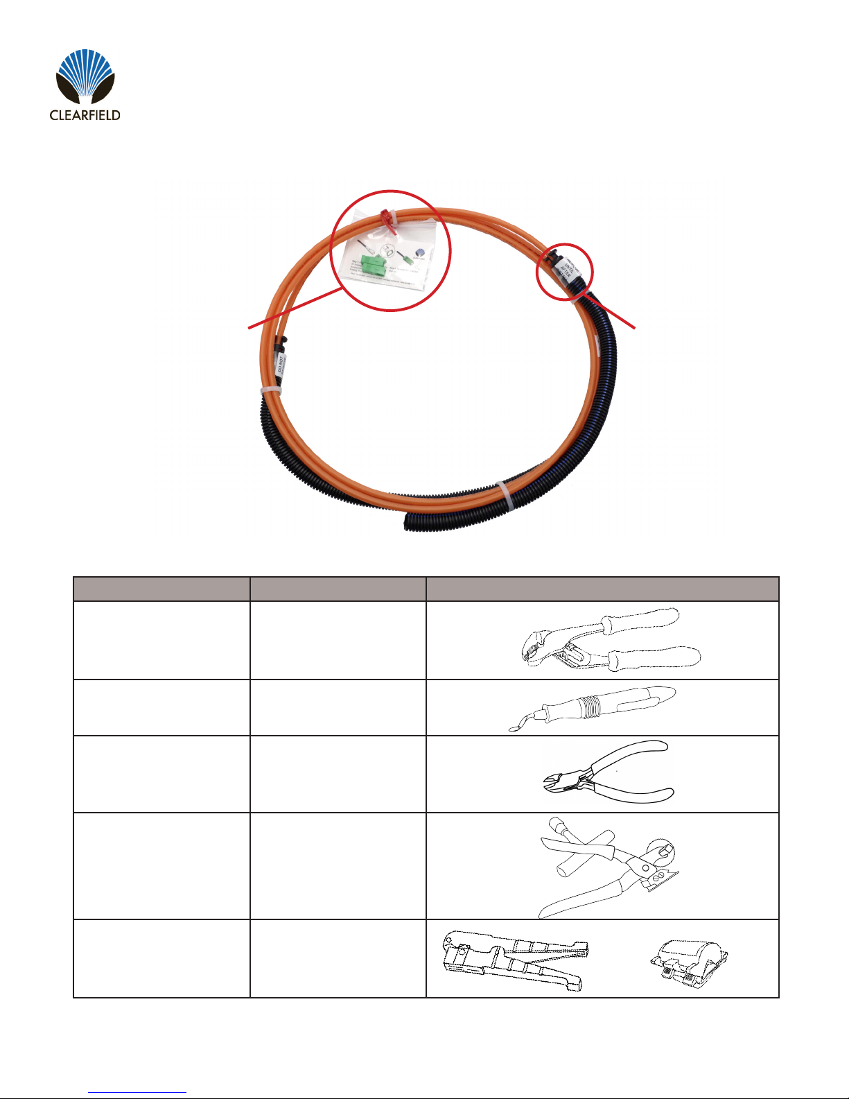
Find No. Tool Image
001 Pliers
002 Deburring Tool
003 Wire Snips
004 Duct Opener
005 Rotary Cutter
Required Tools
Ship along connector parts twist
tied to duct.
Do not remove zip tie
and protective covering
until duct has been direct
buried.
Packaging

Direct: 763.476.6866 • National: 800.422.2537 • www.SeeCleareld.com • [email protected]
6
FieldShield D-ROP
Installation Manual _________________________________________________________
Manual 018958 REV C - Oct 2017
Figure 1 Figure 2
Step 1:Bury Duct
Bury cable according to best practices
for chosen drop method
(Figure 1).
NOTE: Do not remove protective cov-
ering until duct has been buried.
Step 3:Ream Port
Use appropriate tool
(we recommend deburring tool)
to ream and chamfer edges of port
(Figure 3).
Step 2:Remove Flex Port Tab
Use a pair of pliers to snap off tab of
selected Flex Port
(Figure 2).
Figure 2
Installing into YOURx-Terminal
Figure 3
Figure 1
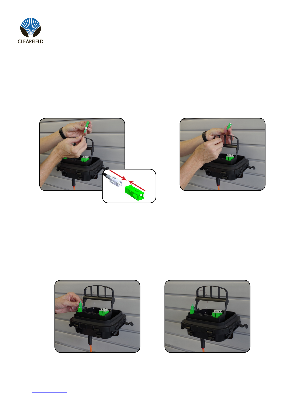
Step 1:Feed Through Flex Port
Guide preconnectorized ber
(unassembled) into YOURx-Terminal
through Flex Port
(Figure 1).
Step 2:Seat FlexConnector
Once ber is through,
seat FlexConnector into FlexPort
(Figure 2)
Preparing Terminal
Seating X-Connector
7
FieldShield D-ROP
__________________________________________________________ Installation Manual
Direct: 763.476.6866 • National: 800.422.2537 • www.SeeCleareld.com • [email protected]
Manual 018958 REV C - Oct 2017
Step 2:Assemble Housing
Push outer housing until it clicks into
place
(Figure 2).
Figure 2
Step 1:Align Connector Housing
Align housing keyway with dot and
push on outer housing
(Figure 1).
Figure 1
Step 1:Seat Connector into FlexCartridge
Connect Fiber to selected port in the
FlexCartridge
(Figure 1 & Figure 2).
Figure 1 Figure 2
Assemble Connector Housing
Connect Fiber to Flex Cartridge

Direct: 763.476.6866 • National: 800.422.2537 • www.SeeCleareld.com • [email protected]
8
FieldShield D-ROP
Installation Manual _________________________________________________________
Manual 018958 REV C - Oct 2017
Figure 1 Figure 2
Step 1:Feed through Port
Guide unassembled preconnectorized
ber into YOURx-TAP FlexPort.
(Figure 1).
Step 3:Assemble SC Connector
Once FlexConnector is seated into
FlexPort, assemble SC Connector
Housing.
(Figure 3).
Step 2:Seat FlexConnector
Once ber is through, seat Flex
Connector into FlexPort.
(Figure 2)
Figure 3
When entering the YOURx-TAP DO NOT assemble SC Connector Outer Housing until ber has
been passed through the port. Fully connectorized ber will not pass through port.
!
IMPORTANT
Installing into YOURx-TAP

9
FieldShield D-ROP
__________________________________________________________ Installation Manual
Direct: 763.476.6866 • National: 800.422.2537 • www.SeeCleareld.com • [email protected]
Manual 018958 REV C - Oct 2017
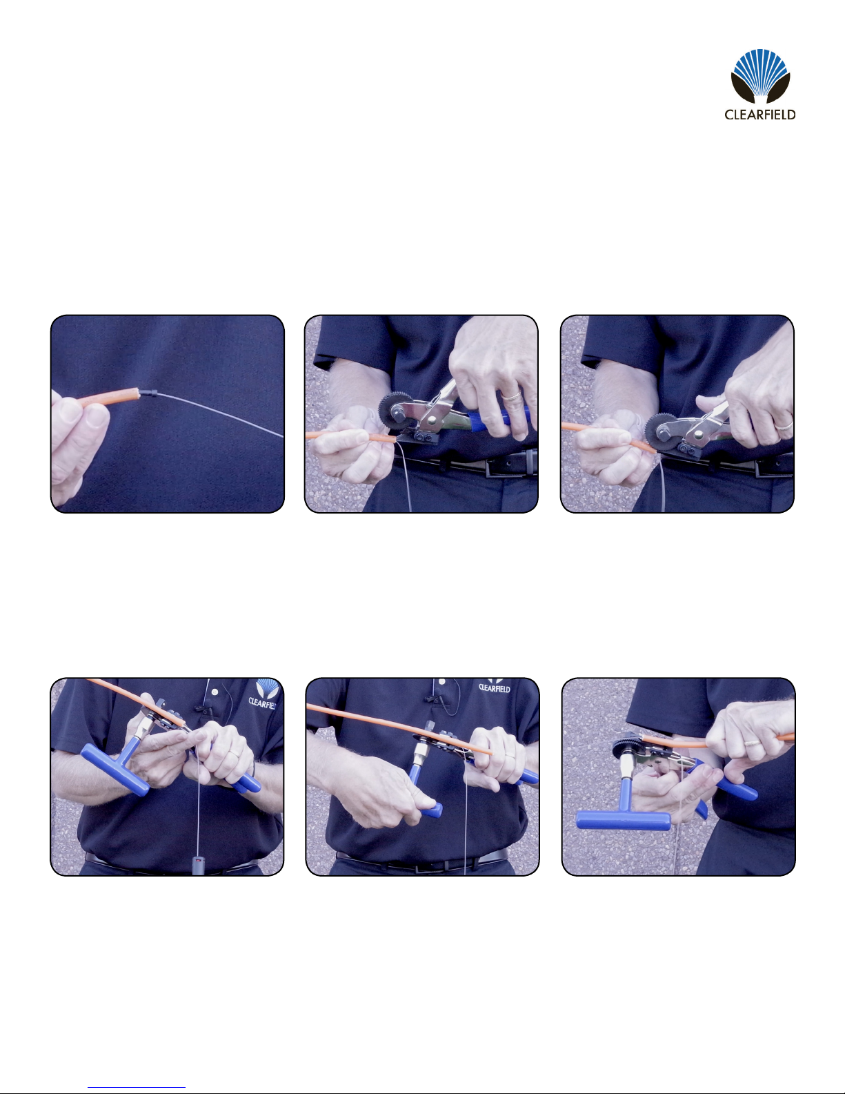
Figure 2Figure 1
Step 1:
Snip zip tie and remove the protective
shipping corrugate (Figure 1).
Step 3:
Use rotary cutter to score duct
(Figure 3).
Step 2:
Working in 6 foot sections or less,
determine desired length and mark
duct (Figure 2).
Figure 3
Reducing Duct Length
Figure 5Figure 4
Step 4:
Bend duct at scoring to break free
(Figure 4).
Step 6:
Remove FLEX connector by pressing
the attached removal tool into the base
of the connector (Figure 6).
Step 5:
Use wire cutters to cut strength
members, taking care not to sever
ber (Figure 5).
Figure 6
Direct: 763.476.6866 • National: 800.422.2537 • www.SeeCleareld.com • [email protected]
10
FieldShield D-ROP
Installation Manual _________________________________________________________
Manual 018958 REV C - Oct 2017
Figure 9Figure 8
Step 8:
Insert tool blade into duct (Figure 8).
Step 10:
Ensure ber is outside of mechanism
(Figure 10).
Step 9:
Squeeze handle to engage traction
gear. (Figure 9)
Figure 10 Figure 12Figure 11
Step 11:
Turn handle to split duct and allow
ber to fall out. (Cut support member if
it interferes with opener’s path.)
(Figure 11).
Step 12:
To nalize the last 1/4 inch of the split,
pull duct across blade by hand
(Figure 12).
Figure 7
Step 7:
Remove ber retainer rubber stop from
the end of the duct (Figure 7).
Questo manuale è adatto per i seguenti modelli
1
Indice
Altri manuali Clearfield Cavi e connettori


