Clearfield FieldShield Manuale utente

FieldShield & FieldShield Flexdrop
Installation Manual ______________________________________________________
Manual 018956 REV A- July 2017
Direct: 763.476.6866 • National: 800.422.2537 • www.SeeCleareld.com • [email protected]
2
FieldShield & FieldShield Flexdrop
Installation Manual _________________________________________________________
Manual 018956 REV A- July 2017
Table of Contents
When to push, pull, or both? 3
Recommended Installation Distances 3
Fiber Installation 4
Attaching Pull String to Fiber 5
Pre-Terminated Pushable LC Drops 6
Pre-Terminated Pushable LC Drops 6
Terminating Fiber 7
Connector Cleaning 7
SC Pushable Connector 9
Simplex LC Pushable Connector 10
Duplex LC Pushable Connector 11
Fiber Polarity Switch 12
Preparing FieldShield Pushable Fiber for
Splice-On Connectors 13
CraftSmart Splice-On Connectors 19
Drop Cable Options 22
Standard Warranty 23
Proprietary Notice 24
Technical Support 24

3
FieldShield & FieldShield Flexdrop
__________________________________________________________ Installation Manual
Direct: 763.476.6866 • National: 800.422.2537 • www.SeeCleareld.com • [email protected]
Manual 018956 REV A- July 2017
When to push, pull, or both?
Every situation is different, but as a general rule, it is typically easier to install
ber using a push and pull combination, rather than pushing or pulling by itself.
By using a combination push/pull method, installers have access to the ber
from both ends of the microduct when troubleshooting.
Recommended Installation Distances
NOTE: If a ber gets stuck or snags during installation, the ber can be pulled back a couple inches from the end being fed into the duct and re-
pulled past the bind point. Sometimes the connector needs to be rocked past a snag point by carefully alternating pushing and pulling from both
ends.

Direct: 763.476.6866 • National: 800.422.2537 • www.SeeCleareld.com • [email protected]
4
FieldShield & FieldShield Flexdrop
Installation Manual _________________________________________________________
Manual 018956 REV A- July 2017
Fiber Installation
Whether pre-connectorized or not, here are a couple quick tips to use when installing pushable ber into the microduct.
These techniques have been used to install single ber, connectorized ber and multi-ber assemblies at distances in
excess of 500 feet.
●Never Remove Protective Cover from Pushable Connectors Prior to Installation
●Pulling is Faster than Pushing
●Pull with Constant Pressure and Speed to Overcome Initial Friction
●Maintain the Same Feed and Pull Rate on Both Ends
If the protective plastic cover is removed from a pre-connectorized pushable
assembly before you place the ber in the microduct, the connector acts as a sort of
“cheese grater” down the length of the microduct. It will shave off the inner liner and
then those particles bind around the ber. In some cases, this causes the ber to
become stuck and usually results in a broken ber.

5
FieldShield & FieldShield Flexdrop
__________________________________________________________ Installation Manual
Direct: 763.476.6866 • National: 800.422.2537 • www.SeeCleareld.com • [email protected]
Manual 018956 REV A- July 2017
Step 2: After the nylon pulling eye has been
slid over the end of the cable, simply tie
the pull string to the loop of the pulling eye
(Figure 3).
Step 1: Slide the open end of the pulling eye over the plastic sheath of the SC Pushable Connector or the
blunt end of the assembly (Figure 1). Make sure to push the assembly all the way to the end of the pulling
eye and pull the pulling eye taut (Figure 2).
Figure 2Figure 1
Figure 3
Note: When using SC Pushable Connectors,
make sure to cut back the excess string left
behind after tying the pull string to the pulling
eye. Failure to remove the excess string can
cause the connector to bind between the
string and the microduct during installation.
Attaching Pull String to Fiber
FieldShield Microduct comes preinstalled with a nylon pull string that can handle pull strengths up to 50 lbs. When attaching
the pull string, never tie the pull string directly to the ber or connector. This will cause damage to or pull the connector off.
Also, never use tape over the string because the outside jacket of the ber is slippery enough that tape usually comes off
and clogs the microduct. Depending upon connector type there are two different methods to attach the pull string to the
pushable ber assembly.
Pre-Terminated Pushable SC and Blunt Drops
The rst method uses a nylon pulling eye that slides over the end of the assembly and works with blunt drops as well as
pre-terminated SC pushable assemblies.

Direct: 763.476.6866 • National: 800.422.2537 • www.SeeCleareld.com • [email protected]
6
FieldShield & FieldShield Flexdrop
Installation Manual _________________________________________________________
Manual 018956 REV A- July 2017
Step 1: Access the pulling eye by sliding the
connector’s protective sheath approximately 1”
towards the opposite end of the assembly, stop-
ping at the metal crimp ring.
Figure 1
Step 3: Make sure that the springs are staggered
one on top of each other then, push the
protective sheath over the connector and knot
from the pull string.
Note: Failure to stagger the springs increases
the width of the pushable connector, making it too
wide to pass tight corners.
Figure 2
Figure 3
Step 2: Tie the pull string to the loop of the
pulling eye and cut back the excess string left
behind.
Note: Do not to cut the string directly at the knot.
Leave about 2 to 3 mms of excess string next to
the knot.
Pre-Terminated Pushable LC Drops
The second method uses a crimped pulling eye that was attached to the assembly during factory termination.
Installation Procedure

7
FieldShield & FieldShield Flexdrop
__________________________________________________________ Installation Manual
Direct: 763.476.6866 • National: 800.422.2537 • www.SeeCleareld.com • [email protected]
Manual 018956 REV A- July 2017
Whether factory terminated or eld spliced, clean connectors are essential
for proper system operation. Even the smallest dust particle can cause
transmission problems, so for optimal network performance, inspect and if
necessary, clean all connectors and adapters prior to mating.
I.T.C…Inspect Then Connect!
ALWAYS inspect the connector rst thing with a clean ber scope inspect
the pair. Three types of contamination require different cleaning techniques.
The use of Chemtronics end face and bulkhead cleaning products and
techniques ensures a clean end face, no matter the type of contamination.
These are Cleareld recommended products/application. Use the product
you feel will complete your cleaning procedures. Create a “best practice” for
your company and follow those procedures.
**NOTE: It is NOT recommended to use IPA to clean the end-face.
Cleaning the end-face…but not just the end-face
• Place one wiping paper on QbE-2 FiberSafe™ Cleaning Platen. Figure 1
• Apply small amount of precision cleaner (about 1” in diameter) with Elec-
tro-Wash MX pen on to one end of the wipe. Figure 2
• Hold end face 90 degree. Adjust for APC connection by slightly tilting the
container or end face. Angle is correct when no drag is left on the end face.
Figure 3
• Draw end face from wet to dry part of the wipe 3 times. Use just enough
pressure to ensure complete contact between end face and the wipe.
DO NOT retrace previous step.
Figure 1
Figure 2
Figure 3
Connector Cleaning Procedure

Direct: 763.476.6866 • National: 800.422.2537 • www.SeeCleareld.com • [email protected]
8
FieldShield & FieldShield Flexdrop
Installation Manual _________________________________________________________
Manual 018956 REV A- July 2017
• CLEAN THE FERRULE…Lightly moisten the ber optic swab
(2.5mm/38542F or 1.25mm/38040) by spotting a small amount (about 1”)
of Electro-Wash PX or Electro-Wash MX pen onto the QBE-2. Hold the
swab, 1 side down to the wetted area and hold for a count of 1-2-3-4-5.
Figure 4
• Insert swab into side of ferrule, wet side to the ceramic ferrule and
circle around 2-3 times and remove. Turn swab to dry side and repeat.
Figure 5
Cleaning the mate through a bulkhead adapter AND the
adapter itself!
• Lightly moisten the ber optic swab(2.5mm/38542F or 1.25mm/38040)
by spotting a small amount (about 1”) of Electro-Wash PX or Elec-
tro-Wash MX pen onto the QBE-2. Hold the tip of the swab onto the
wetted area and hold for a count of 1-2-3-4-5.
• Insert the swab into the adapter to the connector, press lightly against
the connector, twist 2-3 times, remove and discard.
• Dry with a second dry swab.
• Inspect (re-clean if necessary) and test for signal strength.
• Use additional swabs to clean inside the actual adapter. Moisten swab,
like above, insert through hole and remove while twisting. Figure 6
Figure 4
Figure 5
Figure 6

9
FieldShield & FieldShield Flexdrop
__________________________________________________________ Installation Manual
Direct: 763.476.6866 • National: 800.422.2537 • www.SeeCleareld.com • [email protected]
Manual 018956 REV A- July 2017
Cleaning an MPO/MTP Connector
Female Connector
• Place one wiping paper on QbE-2 FiberSafe™ Cleaning Platen and
apply small amount of precision cleaner (about 1” in diameter) with Elec-
tro-Wash MX pen on to one end of the wipe. Figure 1
• Hold end face 90 degree. Adjust for APC connection by slightly tilting
the container or end face. Angle is correct when no drag is left on the end
face. Figure 2
Male Connector
• Lightly moisten the ber optic swab (CC505F) like above, moistening 1
side.
• Place swab, wet side down at one end of connector end-face and draw
across in a diagonal sweep (ie: from ber 1 up and across to ber 12).
Turn swab over to dry and draw back from ber 12 to ber 1. Figure 3
BEFORE cleaning any connector…be sure you know what type of con-
taminate you are cleaning…dry? Fluidic?...All the available products are
good, it’s the process that you need to be aware of. Using a dry cleaning
method to clean “dirt” can lead to scratching of the end-face. Learn the
process of cleaning properly!
Figure 1
Figure 2
Figure 3
Direct: 763.476.6866 • National: 800.422.2537 • www.SeeCleareld.com • [email protected]
10
FieldShield & FieldShield Flexdrop
Installation Manual _________________________________________________________
Manual 018956 REV A- July 2017
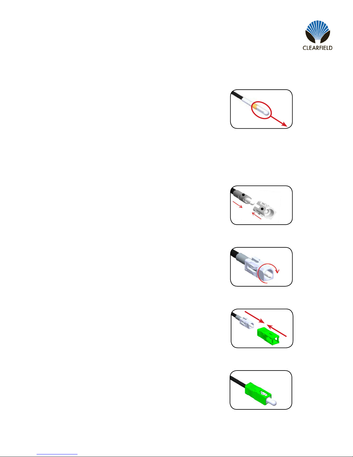
Step 1: Remove the white protective dust cap from the
unassembled connector (Figure 1).
Note: The SC Pushable Connector has a keyed locking
feature that holds the inner housing to the connector and
aligns the ferrule when the two are correctly mated.
To properly mate the connector, the key on the inner housing
must bypass the ferrule alignment notch to properly lock into
place.
Figure 1
Step 3: Rotate counter-clockwise 45 degrees to realign the
inner housing and connector and push the inner housing onto
the connector until it snaps into place (Figure 3).
Step 2: Align the black mark on the inner housing with the
black line on the connector, then rotate the inner housing
45 degrees to offset the lock (Figure 2) and slide the inner
housing half way over the connector.
SC Pushable Connector
Housing Assembly
Figure 2
Figure 3
Figure 4
Figure 5
Step 5: Re-install the white protective dust cap (Figure 5).
Step 4: Align the key on the outer housing with the black line
on the connector, then slide the outer housing over the entire
assembly until it snaps into place (Figure 4).
Questo manuale è adatto per i seguenti modelli
1
Indice
Altri manuali Clearfield Cavi e connettori


