Clearfield FieldShield Assist Manuale utente

FieldShield Assist Module
Installation Manual ______________________________________________________
Manual 017252 Rev A - May 2017

Direct: 763.476.6866 • National: 800.422.2537 • www.SeeCleareld.com • [email protected]
2
FieldShield Assist Module
Installation Manual _________________________________________________________
Manual 017252 Rev A - May 2017
Table of Contents
Product Packaging 3
Parts List 3
Recommended Tools 4
Recommended Installation Distances 5
Microduct Installation Best Practices 6
Assist Module Setup 7
Attaching to Tripod 7
Using the Assist Module 8
Display Settings 10
Setting Distance Counter 10
Setting Inactivity Alarm 11
Assist Module Maintenance 12
Battery Replacement 12
Drive Belt Cleaning 13
Drive Belt Replacement 15
Standard Warranty 16
Proprietary Notice 17
Technical Support 17

3
FieldShield Assist Module
__________________________________________________________ Installation Manual
Direct: 763.476.6866 • National: 800.422.2537 • www.SeeCleareld.com • [email protected]
Manual 017252 Rev A - May 2017
Product Packaging
(Actual packaging may vary.)
Remove packing materials to nd the Assist Module wrapped in a protective bubble wrap sleeve,
with the optional Elevating Tripod and the 1/4” - 20 Thread Metal Mounting Adapter each packaged separately.
Parts List
Part Image
Assist Module
Elevating Tripod (optional item)
1/4” - 20 Thread Metal Mounting Adapter (optional item)

Direct: 763.476.6866 • National: 800.422.2537 • www.SeeCleareld.com • [email protected]
4
FieldShield Assist Module
Installation Manual _________________________________________________________
Manual 017252 Rev A - May 2017
Tool Image
Cordeless Drill
1/4” Drive Socket
#3 Phillips Screwdriver
Recommended Tools

5
FieldShield Assist Module
__________________________________________________________ Installation Manual
Direct: 763.476.6866 • National: 800.422.2537 • www.SeeCleareld.com • [email protected]
Manual 017252 Rev A - May 2017
Recommended Installation Distances
Every situation is different, but as a general rule, it is typically easier to install ber using a push and pull combination, rather
than pushing or pulling by itself. By using a combination push/pull method, installers have access to the ber from both ends
of the microduct when troubleshooting.
NOTE: If a ber gets stuck or snags during installation, the ber can be pulled back a couple inches from the end being fed into the duct and re-
pulled past the bind point. Sometimes the connector needs to be rocked past a snag point by carefully alternating pushing and pulling from both
ends.

Direct: 763.476.6866 • National: 800.422.2537 • www.SeeCleareld.com • [email protected]
6
FieldShield Assist Module
Installation Manual _________________________________________________________
Manual 017252 Rev A - May 2017
Microduct Installation Best Practices
Maintain Minimum Bend Radius of Microducts
FieldShield microducts can be bent down to as little as a 6 inch bend radius before straining the side wall integrity of the
duct. Do not bend microducts tighter than this when cornering as it may cause the conduit to kink. If space permits, it is
always best to use two sweeping 45° turns rather than one 90° turn.
De-Burr Between All Coupled Microduct Joints
Prior to coupling two microducts, make sure to prepare the face of each microduct by de-burring the inside bore to a cone
shape.
Properly de-burring the bore of the microduct reduces the chance of the ber or pull string getting stuck or snagging when
passing through the microduct coupler.
Consult Local Regulations for Installation Depths and Restoration Procedures
The depth microducts can be buried will vary depending upon local conditions and regulations. Under all conditions, the
microduct should be buried at a depth that will provide adequate protection during the frost cycle.
Rocks and debris should never be left in the bottom of a trench. If soil is predominently coarse with many rocks present, the
bottom of the trench should be bedded prior to microduct placement. Backlling with a ner grade of material such as sand
will ll the voids between the duct and sidewwall and provide additional strength.
Pull Additional Microduct to Access Pull String
When installing microduct into a terminal or splice enclosure make sure to pull an extra 5 to 10 feet of microduct through the
installation port to expose and access the integrated pull string. If ber is not being installed at the same time, make sure to
tape the pull string to the outside of the duct, prior to capping the duct.
Validate Microduct and Fiber Installation Prior to Restoration
When application permits, it is always best to install the ber and ensure that it is working prior to restoring the installation
path. This provides the most exiblity when troubleshooting is required and eliminates restoration rework if obstacles arise.
If ber is not being installed at the same time as the microduct, but instead is being installated by a separate crew or when
the customer turns-on service, the microduct path should be validated or proofed to ensure that the path is capable to install
ber at a later date.

7
FieldShield Assist Module
__________________________________________________________ Installation Manual
Direct: 763.476.6866 • National: 800.422.2537 • www.SeeCleareld.com • [email protected]
Manual 017252 Rev A - May 2017
Step 3: Attach Mounting Adapter
To avoid accidently stripping the thread,
rst attach the ¼”-20 thread metal mounting
adapter to the FieldShield Assist Module
(Figure 3).
Assist Module Setup
Attaching to Tripod
Watch the Installation Video
for the FieldShield Assist Module
https://youtu.be/WjdPfFMqEqk
Step 4: Attach Tripod Housing to Tripod
Slide the threaded tripod adapter over the tripod. Then, tighten the wing nut to clamp the Assist
Module in place on the tripod.
Step 1: Unpack Elavating Tripod
Remove tripod from packaging and set aside
the ¼”-20 thread mounting adapter packaged
along with the tripod (Figure 1).
Figure 2Figure 1
Figure 4Figure 3
Step 2: Remove Tripod Housing
Remove the the 5/8”-11 thread tripod housing
from the tripod (Figure 2).
Step 4:Attach Tripod Housing
Screw 5/8”-11 thread tripod housing onto the
metal thread adapter (Figure 4).

Direct: 763.476.6866 • National: 800.422.2537 • www.SeeCleareld.com • [email protected]
8
FieldShield Assist Module
Installation Manual _________________________________________________________
Manual 017252 Rev A - May 2017
Step 1: Open the Assist Module
Lift up on the hinged top of the FieldShield Assist
Module (Figure 1).
Figure 1
Using the Assist Module
Step 3: Insert Microduct
Insert the microduct into the retention clamp.
Make sure to stop before the ber guide groove.
Tighten the two #3 screws on the retention
clamp to hold the microduct in place during ber
installation. (Figure 3)
Figure 2
Figure 3 Figure 4
Step 4: Insert Fiber
Insert 2 to 3 inches of the pushable ber
assembly into the microduct and align the ber in
the groove of the ber guide. (Figure 4)
Step 2: Loosen Retention Clamp
Loosen the two #3 Philips head screws from the
green retention clamp (Figure 2).
NOTE: The screws do not need to be entirely removed from
the top of the retention clamp to insert the microduct.
NOTE: When using Direct Buried Toneable or Aerial
Figure-8, strip back the tone wire or strength member at
least 6 inches prior to inserting the duct into the retention
clamp.

9
FieldShield Assist Module
__________________________________________________________ Installation Manual
Direct: 763.476.6866 • National: 800.422.2537 • www.SeeCleareld.com • [email protected]
Manual 017252 Rev A - May 2017
Step 5: Close the Assist Module
Close the case and clamp the clam shell lock
closed on the front of the assist module, mak-
ing sure that the ber stay in the ber guide
grooves(Figure 5).
Figure 5
Step 7:Feed Fiber into Microduct
Use a ¼” drive socket to power the assist module
and feed the ber into the microduct (Figure 7).
Make sure to maintain a consistent speed when
powering the cordless drill.
Figure 6
Figure 7
Step 6: Enable Distance Counter
Open the glare resistant display cover and press
the power button on the right to enable the instal-
lation distance counter (Figure 6).
NOTE: The default unit of measurement for the assist
module distance counter is standard (feet), but can be
switched between standard and metric units.
Step 8: Reset Distance Counter
Once the ber has been installed, reset the
counter switch on the FieldShield Assist Module
by turning the power button off, then powering
back on to continue with the next cable install.
NOTE: To maximize installation distances, feed the ber
off the spool at the same rate as the ber being installed
through the FieldShield Assist Module. Failure to keep ber
installation rates consistent and constant may increase the
amount of friction on the ber during installation.
When using the Assist Module, pay
close attention to the clutch. If the
clutch begins to slip, reduce drill
speed to minimize heat build up.
Failure to reduce drill speed may
cause the Assist Module to fail.
!
IMPORTANT
Direct: 763.476.6866 • National: 800.422.2537 • www.SeeCleareld.com • [email protected]
10
FieldShield Assist Module
Installation Manual _________________________________________________________
Manual 017252 Rev A - May 2017
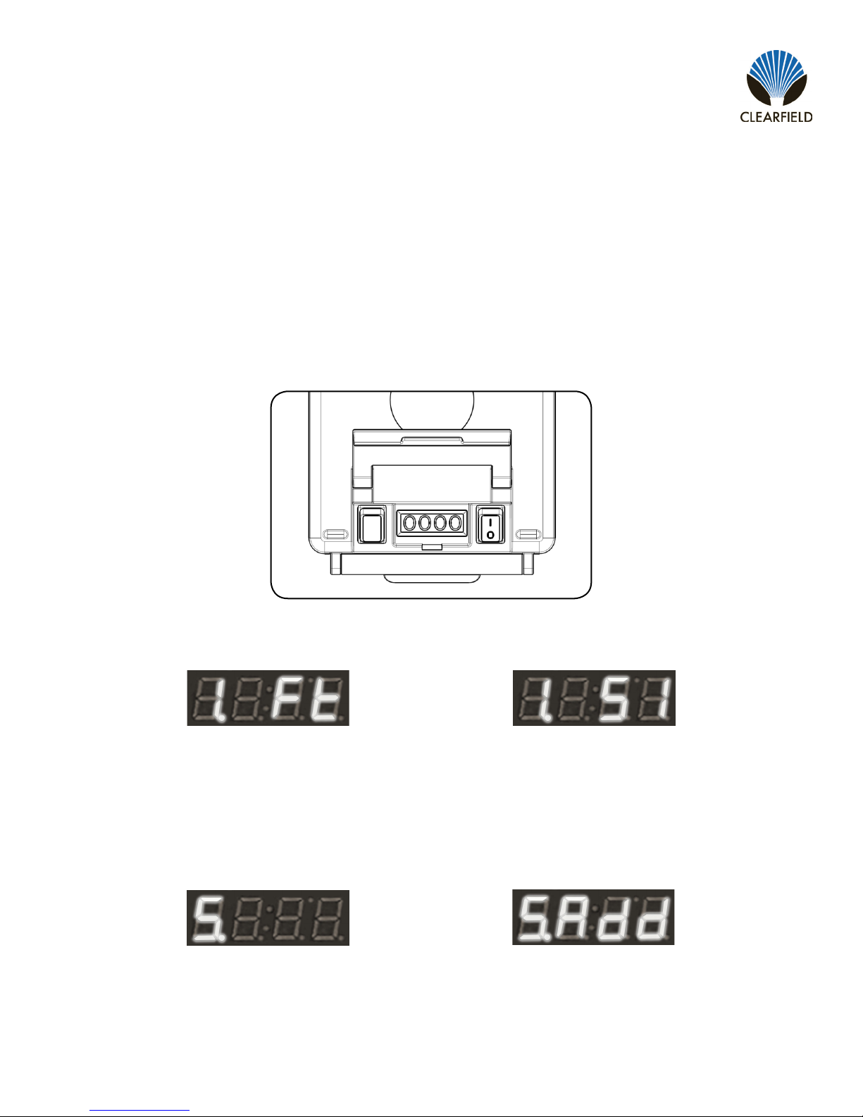
Step 1: Lift the glare resistant screen cover. Press the power button on the right side on the display to turn the assist
module on (Figure 1). Then press the settings button on the left to enter the menu.
NOTE: The screen will display the current unit of measurement as Ft (Feet) for Standard and SI (System International) for Metric.
Figure 1
Display Settings
The FieldShield Assist Module is equipped with a glare resistant distance counter to instantly provide the installer with
accurate installation distances. By default, all FieldShield Assist Modules are set with the unit of measurement as Feet or
Standard.
Setting Distance Counter
Step 2: Slide the top drive belt on the inside of the assist module left (Figure 2) or right (Figure 3) to switch between units.
Figure 2 Figure 3
Figure 4 Figure 5
Step 3: Once the screen displays the correct unit of measurement, press the settings button four times until the screen
displays the number 5 (Figure 4). At that time, slide the top drive belt to the right until the screen displays “5. Add”
(Figure 5).
NOTE: “Add” indicates that, upon pressing the settings button, changes will be saved to the memory. Turning the unit off at this point
before saving will discard all changes.
Step 4: Press the settings button once to save the current settings. After the settings have been saved, the display will
switch back to displaying the counter.
Indice
Altri manuali Clearfield Unità di controllo


Manuali Unità di controllo popolari di altre marche

Festo
Festo Compact Performance CP-FB6-E Manuale elenco delle parti

Elo TouchSystems
Elo TouchSystems DMS-SA19P-EXTME Manuale utente

JS Automation
JS Automation MPC3034A Manuale utente

JAUDT
JAUDT SW GII 6406 Series Guida rapida

Spektrum
Spektrum Air Module System Manuale utente

BOC Edwards
BOC Edwards Q Series Manuale utente


