CNC4PC UC300ETH Manuale utente

___________________________________________________________________________
USER’S
MANUAL
VER.1
C76- MULTIFUNCTION CNC BOARD
Rev. 3
OCTOBER 2021

___________________________________________________________________________
Contents Page #
FEATURES.....................................................................................................................3
I/O SPECIFICATIONS.....................................................................................................4
BOARD DESCRIPTION..................................................................................................5
POWER TERMINALS AND CONFIGURATION JUMPERS............................................5
4.1 Power terminal...........................................................................................................5
4.2 Source Output 5VDC.................................................................................................6
4.3 Source Output 10-24VDC..........................................................................................6
4.4 Input terminals for port_1 and port_2 ......................................................................6
4.5 Select inputs of port_1 and port_2...........................................................................7
JUMPER POSITION .......................................................................................................9
5.1 Selecting the SCHP operation mode........................................................................9
5.2 Jumper configuration driver enable.......................................................................10
5.3 Jumper configuration driver fault...........................................................................10
5.4 Configuration jumper pin 16 or 17.........................................................................10
LPT_3 AND LPT 5 INPUT EXPANSION PORT............................................................11
LPT_4 OUTPUT EXPANSION PORT ...........................................................................12
ANALOG I/O PORT PINOUT........................................................................................13
CONNECTION EXAMPLE FOR SHIELD C78 ..............................................................14
9.1 RJ45 shield C78 connection for axes, Limits and Encoder..................................14
9.2 RJ45 shield board description................................................................................14
9.3 Pinout.......................................................................................................................15
CONNECTION EXAMPLE FOR SHIELD C77 ..............................................................16
10.1 Terminal Shield Screw-on.......................................................................................16
10.2 Shield board description.........................................................................................16
DRIVER DISCONNECTION JUMPERS........................................................................17
E-STOP TERMINAL......................................................................................................17
TYPICAL CONNECTIONS............................................................................................18
LED INDICATOR ..........................................................................................................19
WIRING SAMPLE ENCODER ......................................................................................21
DIMENSIONS................................................................................................................22

___________________________________________________________________________
USER'S MANUAL TABLE OF CONTENTS
FEATURES
•Designed for UC300ETH motion controller.
•3 Expansion Ports. It has 3 x IDC26 connector for adding Breakout or
Relay Boards.
•Built-in PWM-Based Speed Control and Two Built-in Electromechanical
Relays with NO and NC positions for spindle control.
•The system monitors:
-E-Stop
-Safety Charge Pump.
-VFD Fault.
-Driver Fault.
•Outputs can be 500mA open collector or +5vdc at 50mA TTL.
•Electromechanical Relay with NO and NC positions for general purpose
(Port_2 16 or 17, jumper-selectable).
•Microcontroller based SCHP.
•Optoisolated inputs working at 5-24VDC.
•Can be powered with a voltage between +10 and +24VDC.
•Status LEDs on all input and Output connections.
•DIN Rail mountable.
•Pluggable Screw-On Terminals.
•It is compatible with family of C34 connector boards that allow quickly
connecting to popular drives connecting not just the step and direction
signals, but also the fault and enable signals.
•High speed input *New
___________________________________________________________________________
I/O SPECIFICATIONS
Inputs and Outputs are jumper selected to be TTL or Open collector.
PINS
PORT1
PORT2
PORT3
PORT4
PORT5
TOTAL
INPUT
5
13
13
5
13
49
OUTPUT
12
4
4
12
4
36
TOTAL
17
17
17
17
17
93
OPTOISOLATED DIGITAL INPUT TTL SPECIFICATIONS
On-state voltage range
5 to 24VDC
Maximum off-state voltage
0.8V
Typical signal delay
2.8uS
DIGITAL OUTPUT TTL SPECIFICATIONS
Maximum output voltage
5VDC
Maximum output current
24mA
Maximum off-state voltage
0.44 V
Maximum supported frequency
400KHz
Typical signal delay
10nS
Time of transition to high impedance state
12nS

___________________________________________________________________________
BOARD DESCRIPTION
POWER TERMINALS AND CONFIGURATION JUMPERS
4.1 Power terminal
The board requires an external power supply which can deliver 10-24VDC@700mA to power
the logic of the board and the UC300, but keep in mind that each output can deliver up to
500mA and if powering other breakout or relays boards. So, you will need to add all the
expected power consumption.

___________________________________________________________________________
4.2 Source Output 5VDC
4.3 Source Output 10-24VDC
10-24VDC can be sourced to sensors or other cards requiring it.
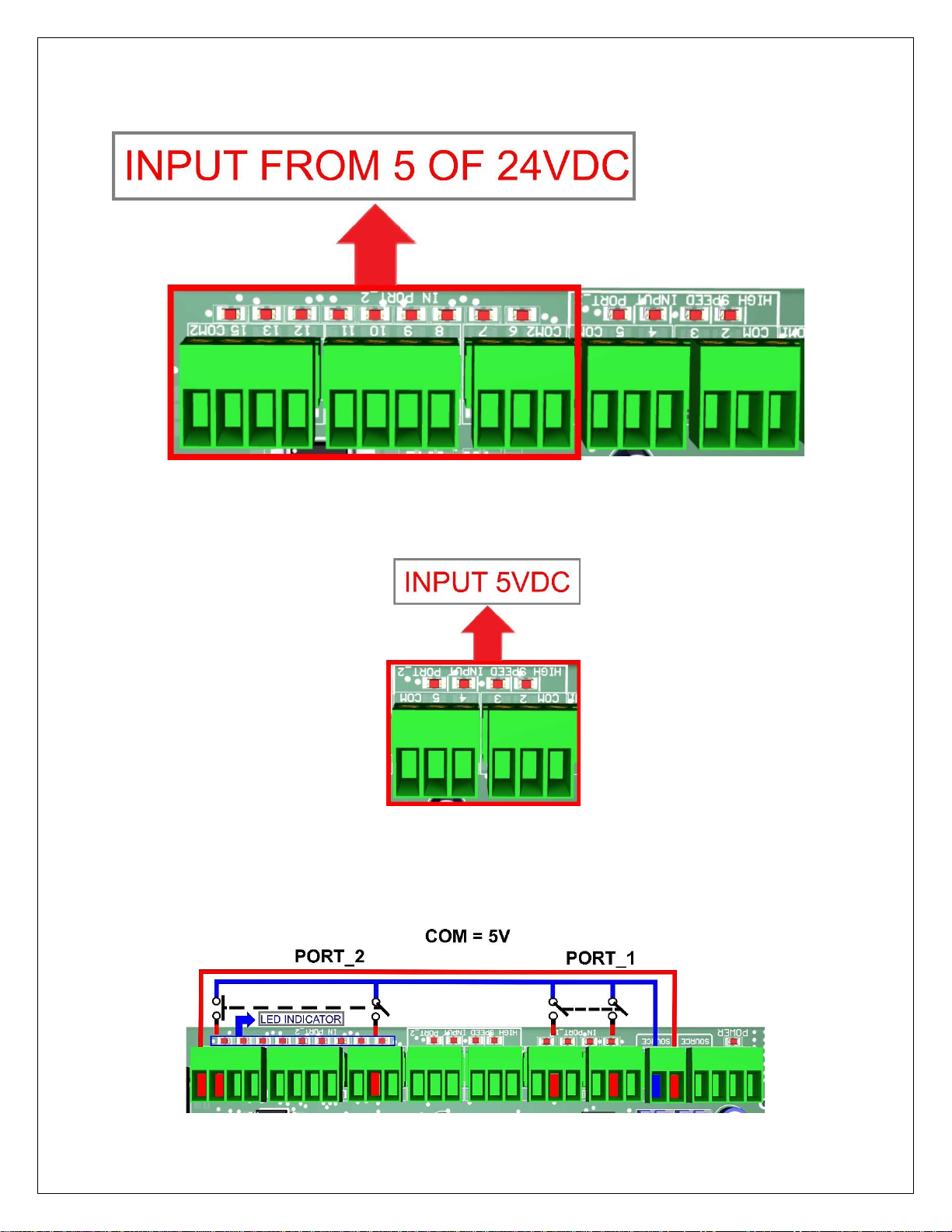
4.4 Input terminals for port_1 and port_2
These terminals support signals 10-24VDC, you can connect sensors NPN, PNP, switches,
capacitive sensors, etc. set jumpers depending on signal voltage.
PORT_1
___________________________________________________________________________
PORT_2
HIGH SPEED INPUT PORT_2 PIN 2, 3, 4 AND 5
These terminals support signals 5VDC
4.5 Select inputs of port_1 and port_2
Set the Jumper to COM = +5VDC, GND or 10-24VDC to determine the common for the input
signals to be used.

___________________________________________________________________________

___________________________________________________________________________
JUMPER POSITION
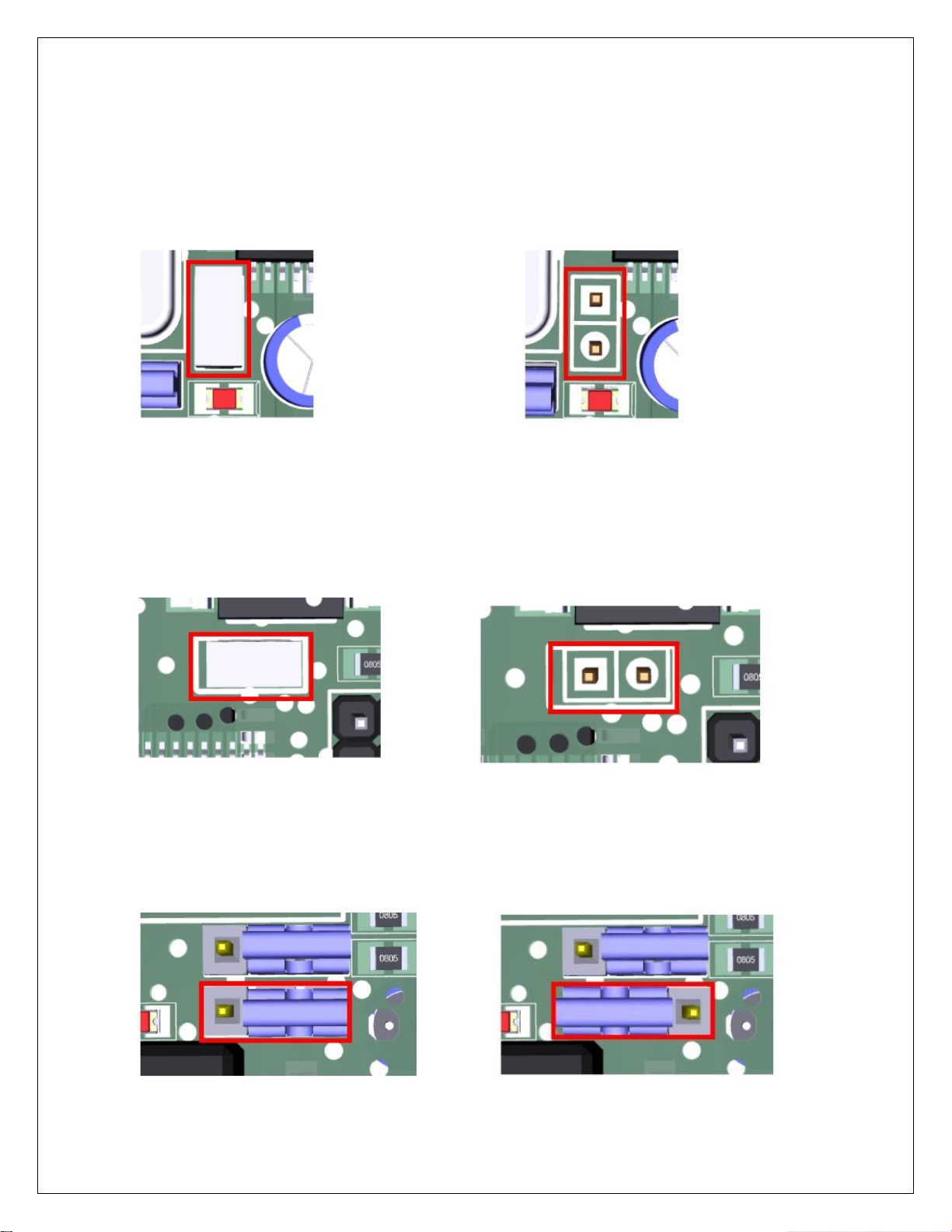
5.1 Selecting the SCHP operation mode
The Safety Charge Pump uses pin 17 on port 2. When the SCHP is enabled on the board, then
the output of the terminals will be active while the Safety Charge Pump signal is present and
inactive while the SCHP is not present.
1-2: SCHP ON 2-3: SCHP OFF
Note: also, that Relay3 on can also be tied to pin 17 or 16 on port 2. If the jumper is set
to be tied to pin 17, then the relay will activate while the system is active. This can be
ideal to control power to DC servos or to handle servo brakes. Or enable/disable any
other feature that is associated to the system been active.
___________________________________________________________________________
5.2 Jumper configuration driver enable
When you need to use the Driver enable to ON put the jumper, if you need it OFF remove the
jumper
1-2: Driver enable ON 2-3: Driver enable OFF
5.3 Jumper configuration driver fault
When you need to use Driver Fault to ON set the jumper, if you need to OFF remove the
jumper.
1-2: Driver fault ON 2-3: Driver fault OFF
5.4 Configuration jumper pin 16 or 17
1-2: PIN16 2-3: PIN17
Questo manuale è adatto per i seguenti modelli
2
Indice
Altri manuali CNC4PC Unità di controllo

Manuali Unità di controllo popolari di altre marche

Festo
Festo Compact Performance CP-FB6-E Manuale elenco delle parti

Elo TouchSystems
Elo TouchSystems DMS-SA19P-EXTME Manuale utente

JS Automation
JS Automation MPC3034A Manuale utente

JAUDT
JAUDT SW GII 6406 Series Guida rapida

Spektrum
Spektrum Air Module System Manuale utente

BOC Edwards
BOC Edwards Q Series Manuale utente


