Comtek BST-75 Manuale utente
Synthesized
Base Station
Transmitter
BST-75 OPERATOR’S MANUAL (72-76 MHz)
357 West 2700 South • Salt Lake City, Utah 84115 • Phone: (800) 496-3463 • Fax: (801) 484-6906 • www.comtek.com

© 2005 COMTEK®All rights reserved
Printed in U.S.A. 11-02-09
TABLE OF CONTENTS
Introduction ...........................................................
Equipment Placement ...............................................
Power Requirements .......................................................
Remote Antenna ......................................................
Screw-in Whip Antenna ............................................
Audio Input Connections ...............................................
Audio Adjustments ...............................................
Audio Processing Circuit ..........................................
Front and Rear Panel Facilities ........................................
Frequency Information ..........................................
Accessories ..........................................................
Specifications ......................................................
Warranty and Service ...............................................
1
2
2
3
3
4
4
5
6-7
8-9
10-11
12
13

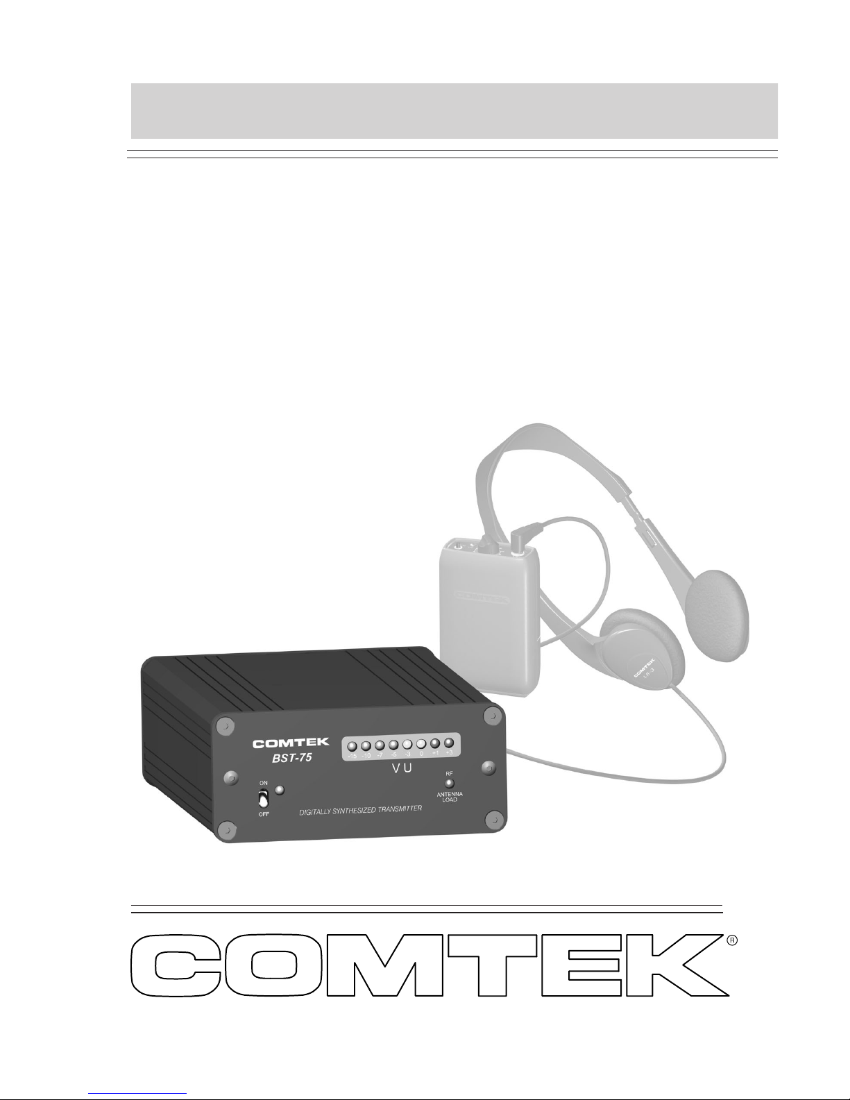
TheBST-75 mini base station transmitter meets the highest
professional standards while offering outstanding value
and the most advanced technology available. This versatile and
innovative transmitter is simple to use, yet it has sophisticated
features such as “Flash Memory” 98-channel programmability
with synthesized manual 10-channel selectable user-switch. Plus
a unique multi-function R.F. indicator detects bad antenna load, RF
presence, coaxial cable short or open condition for quick and easy
trouble-shooting.
The compact design of this transmitter is ideal for multiple transmitter
installations. Up to four transmitters can be installed in one rack
space. Also, it operates in the 72-76 MHz band under FCC Regulation
Part 90. This allows a greater RF power capability (120 mW) for greater
range and reliability than customary FCC Part 15 systems.
The audio processing circuit produces full fidelity frequency response
from 80 Hz to 10 kHz with very low residual F.M. noise and distortion.
To accommodate a greater variety of receivers, the BST-75 can operate
with non-companded receivers or with companded receivers for higher
fidelity sound reproduction with a signal-to-noise ratio ofupto100 dB.
All this is designed into a stylish, compact, all-metal enclosure suitable
for permanent rack-mount installations or for stand-alone portable
applications.
INTRODUCTION
BST-75
Synthesized
Base Station
Transmitter
Page 1
Equipment Placement
If the BST-75 base station is to be rack mounted, a remote antenna must
be used. The base station should be mounted away from equipment
that uses large power transformers to reduce 60 Hz hum possibilities.
Special Note: When using the base station in close proximity to other
audio equipment, ensure that the audio equipment is notsusceptibleto
RFinterference. Thiscanbeaccomplished by temporarily installing
the base station as per above, and then while the base station is
operating, checking all audio outputs for uncharacteristic noise. If a
problem is found, move the base station or the remote antenna as far as
possible from the affected equipment. Should you continue to have
problems, contact COMTEK’s Technical Support Services for
assistance.
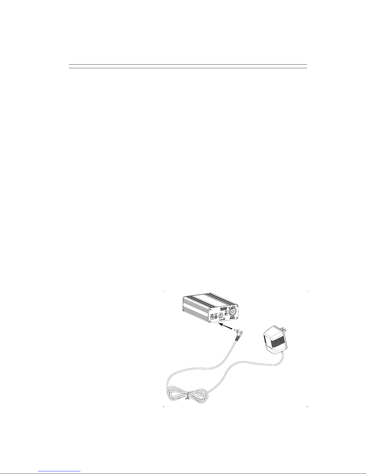
Power Requirements
The BST-75 base station is designed to be powered by 12 voltsAC
through a standard barrel type power jack (5.5mm X 2.1mm). The
AC power adaptor supplied (AP-12VAC) is used for permanent
installations and mobile applications
where AC power is available.
For field operation only, the
BST-75 base station will accept
12V DC through the power jack
with either positive or negative
12V to the center pin of the jack.
The on/off switch on the front
panel of the base station
transmitter should be
turned to the “off”
position when the power
plug is initially plugged
intothe transmitter.
Page 2
OPERATING INSTRUCTIONS
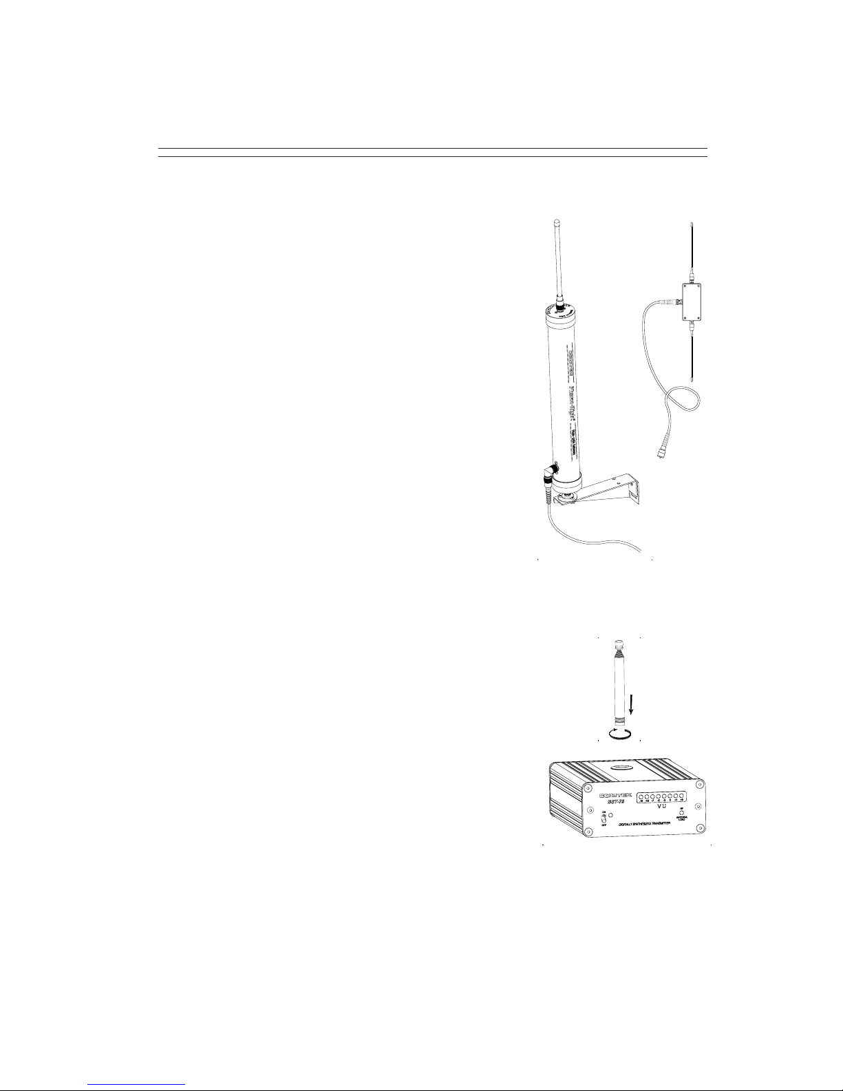
Remote Antenna
When the BST-75 base station transmitter
is to be rack mounted for permanent
installation, a remote antenna must
be used. The RDA-2B remote dipole
antenna (or equivalent) or the COMTEK
“Phase Right Antenna” PRA-L72 high
performance omni antenna should be
used. These antennas must be placed
vertically polarized up to twenty feet
away from the transmitter with the
coaxial cable supplied. The highest
possible antenna placement away from
any metallic object is best. For high gain
directional yagi type antennas and
specialty antennas, contact COMTEK’s
Technical Support Services.
Integral Screw-in Whip Antenna
If the BST-75 base station transmitter is to be
used outside of the traditional rack-mounted
environment for stand-alone mobile type
applications, the screw-in whip antenna
(TWA-75) should be used. The transmitter
should be placed on a table or platform as
high as possible so the fully extended
whip antenna is at least 24” away from
any metallic object. The radiated output
power of the transmitter with this whip
antenna will not be as great as the remote
antennas. The BST-75 transmitter should
only be used in the high power setting when
the telescoping whip antenna is used.
Page 3
OPERATING INSTRUCTIONS
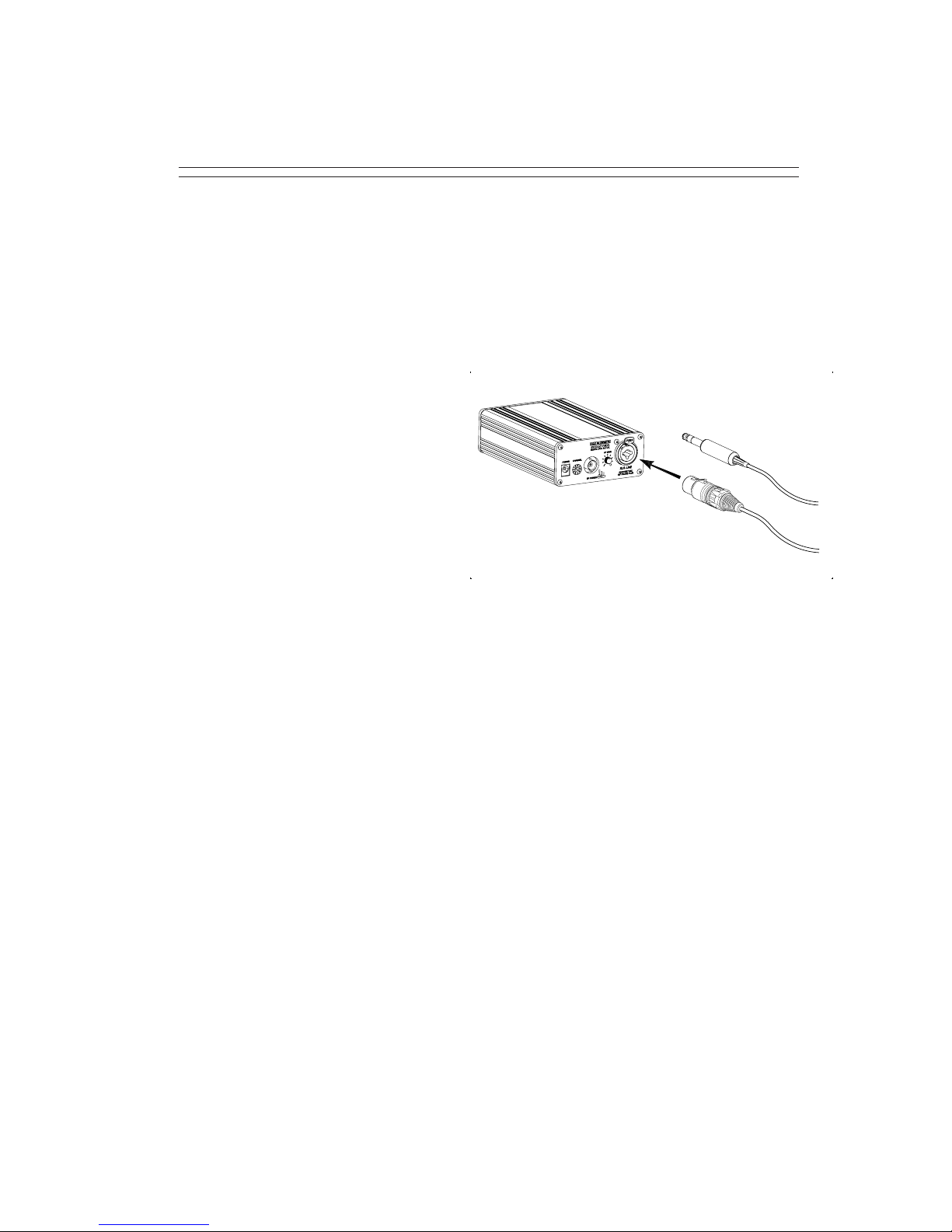
Audio Input Connections
The BST-75 base station transmitter uses an XLR-3F connector with a
“Combo” phone jack. The XLR portion of the connector will accept a
true balanced or unbalanced line level signal up to +20 dBm. The
1/4” phone jack portion of the connector is a dedicated input for a
phantom-powered,two-conductor Electret microphone. The
HM-100 1/4” behind-the-neck
directionalboom microphone
is normally used for language
interpretation, but any two-
conductorElectret microphone
may be used in this input.
AudioAdjustments
In order to ensure the highest possible transmission fidelity, the
transmitter must be modulating at least 50% with normal speech
(0 dB on the VU meter). This adjustment is made in the following
manner:
a. Ensure that the audio source has been optimized for best
signal-to-noise ratio.
b. The XLR-3 connector located on the back of the transmitter is
usedfor line levelbalanced orunbalanced audiosource (0 to +20 dBm).
c. Set the AF Gain Control on the back of the base station to fully
counterclockwise and then, while normal program information is
present, slowly rotate the “LEVEL” control clockwise until the VU
meter on the front panel begins to deflect. Adjustment should be made
so that normal speech or music deflects the 0dB yellow LED. Only very
loud speech or music should deflect the VU meter full-scale into the
last red LED.
Page 4
OPERATING INSTRUCTIONS

OPERATING INSTRUCTIONS
Audio Processing Circuit
The audio processing system incorporates a peak-level compressor to
prevent over-modulation and reduce audio distortion at high levels.
This compressor has a very fast attack time and a carefully controlled
decay time to optimize the dynamic performance of the audio process-
ing system. (The VU meter will indicate this compressor action when
the red LEDs are illuminated.) The audio is also equalized to add
pre-emphasis as well as a very sharp high frequency roll-off circuit to
minimize high frequency noise in the audio signal. The total frequency
responseand performance ofthe system is, however, determined bythe
corresponding de-emphasis and equalization used in the receiver.
Inorderto accommodatea greater variety of receivers,the BST-75
transmitter incorporates the option to operate with receivers that have
companded or non-companded audioprocessing. However,theBST-75
transmitter must operate non-companded with non-companded
receivers and companded only with receivers that incorporate
companding processing. Amismatch will result in unacceptable audio
performance. BasicCompandingTheory
The dynamic range of the audio signal is compressed in the transmitter
at a 2:1 ratio. The receiver then expands the audio signal at a comple-
mentary 1:2 ratio to restore the dynamic range of the audio signal to the
original level and also to provide additional noise reduction when no
audio signal is present.
Page 5
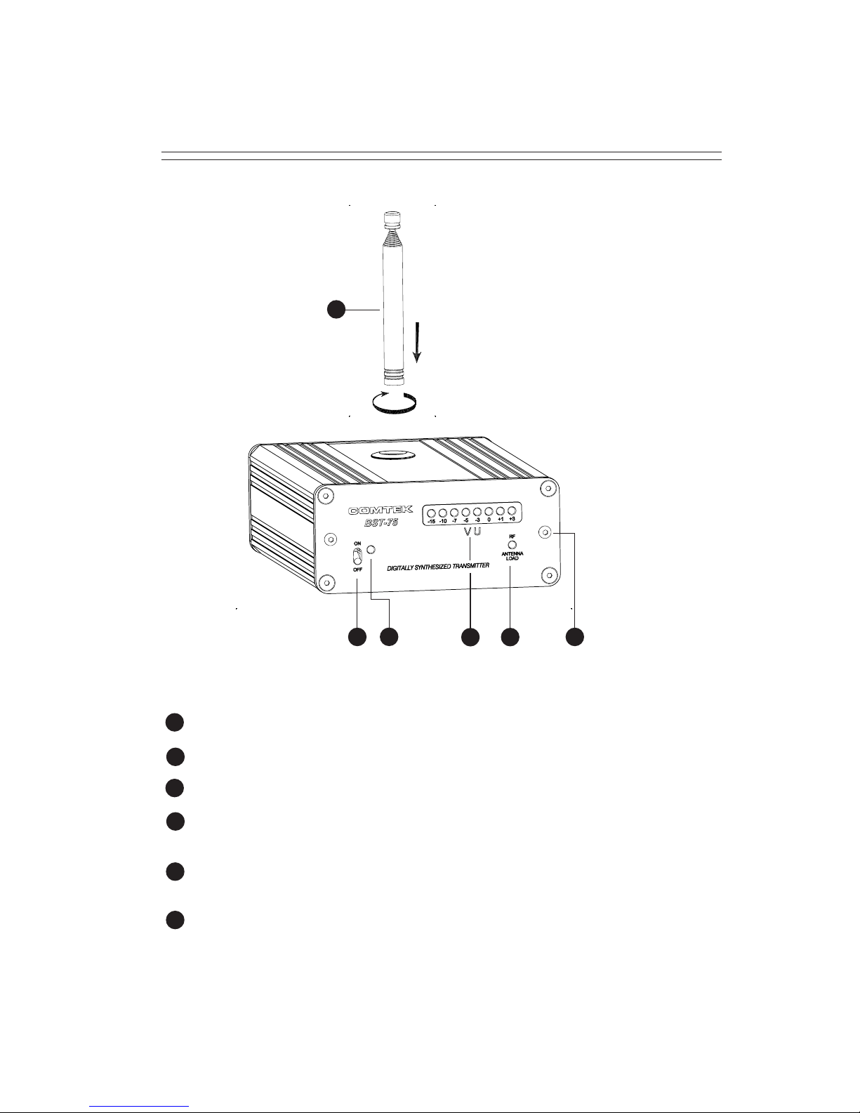
OPTIONAL ANTENNA: Used for mobile type applications.
POWER SWITCH: Turns the transmitter on or off.
POWER LED INDICATOR: Illuminates when the power is on.
VU METER: Displays the audio level being used for modulation.
(See Audio Adjustment Section.)
ANTENNA INDICATOR: Flashes when transmitter detects coaxial
cable shorts and open conditions, bad antenna load.
RACK-MOUNTING SCREWS: Used for mounting BST-75 to
rack-mounting panels.
BST-75 FRONT PANEL
Page 6
4
3
2
1
3 54
2 6
5
1
6
12
7
8
9
10
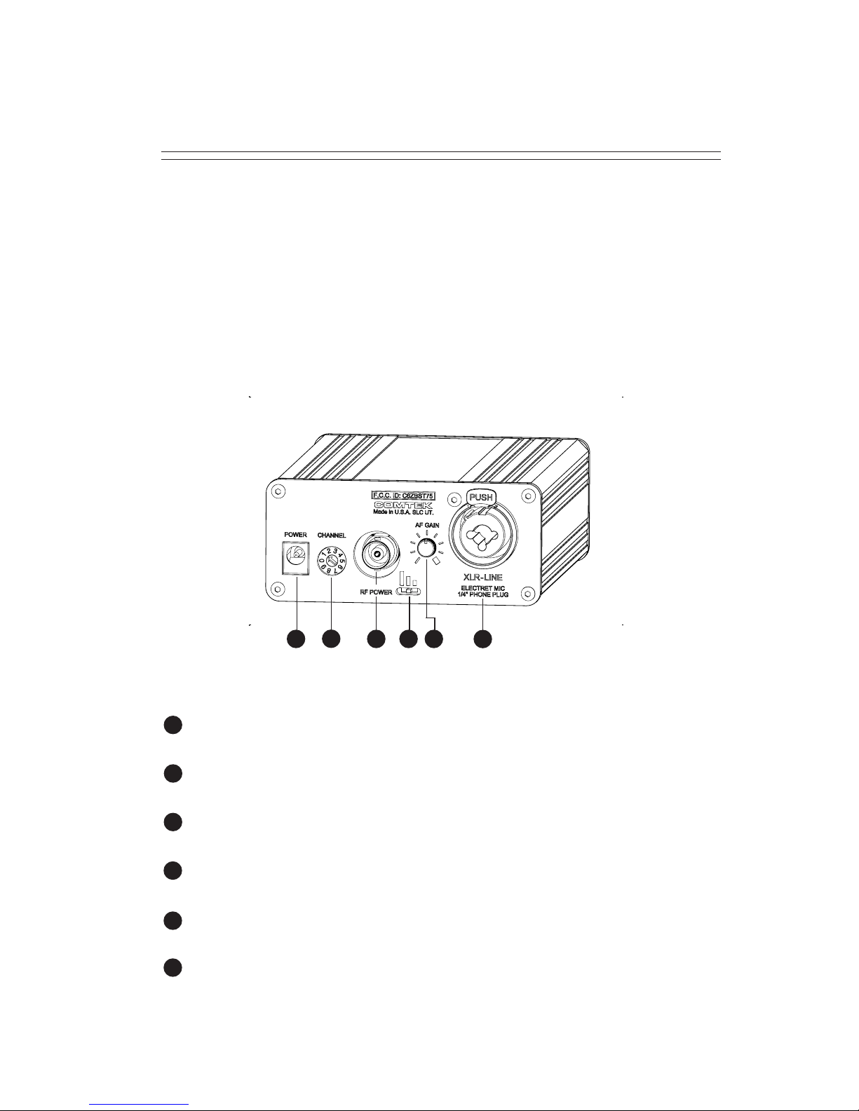
BST-75 REAR PANEL
POWER INPUT JACK: Requires 12V AC at 200 mA. Will also accept 12V
DC with either positive or negative center pin (for field operation only).
CHANNEL SELECTOR SWITCH: Selects the frequency on which the
transmitter will operate. (See Frequency Information Section.)
EXTERNAL ANTENNA JACK: BNC connector provides a standard
50 ohm RF output for use with an external antenna.
RF POWER SWITCH: Adjusts the RF power output of the transmitter
(High-120mW, Mid-40mW, Low-10mW).
AUDIO LEVEL CONTROL: This control is used to set the proper
modulation level when referenced with the VU meter.
MIC / LINE AUDIO INPUT: XLR-3 accepts balanced line level input.
1/4” phone jack accepts 2-conductor electret microphone type only.
11
Page 7
710912811
Page 8
CHANNEL FREQUENCY
A #1
B #2
C #3
D #4
E #5
F #6
G #7
H #8
I #9
J #10
72.1 MHz
72.3 MHz
72.5 MHz
72.7 MHz
72.9 MHz
75.5 MHz
75.7 MHz
75.9 MHz
74.7 MHz
75.3 MHz
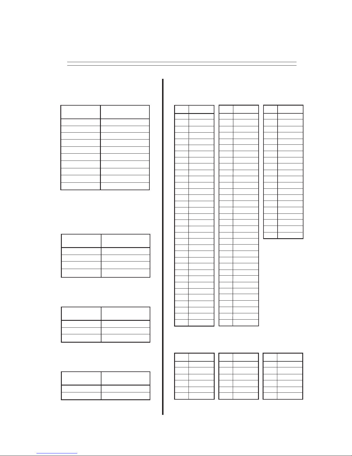
USER-SWITCHABLE
STANDARD CHANNELS
NON-COMPANDED
AVAILABLE 72-76 MHz
“FLASH MEMORY”
COMPANDED CHANNELS
BST-75 FREQUENCY INFORMATION
CHAN FREQ
72.02 MHz
72.04 MHz
72.06 MHz
72.08 MHz
72.10 MHz
72.12 MHz
72.14 MHz
72.16 MHz
72.18 MHz
72.20 MHz
72.22 MHz
72.24 MHz
72.26 MHz
72.28 MHz
72.30 MHz
72.32 MHz
72.34 MHz
72.36 MHz
72.38 MHz
72.40 MHz
72.42 MHz
72.46 MHz
72.50 MHz
72.54 MHz
72.58 MHz
72.62 MHz
72.64 MHz
72.66 MHz
72.68 MHz
72.70 MHz
72.72 MHz
72.74 MHz
72.76 MHz
72.78 MHz
GROUP 1 GROUP 2 GROUP 3
FREQUENCY
72.1 MHz
72.9 MHz
75.9 MHz
75.3 MHz
GROUP FREQUENCY CHART
GROUP 1
CHANNEL
A #1
E #5
H #8
J #10
FREQUENCY
72.3 MHz
75.7 MHz
74.7 MHz
GROUP FREQUENCY CHART
GROUP 2
CHANNEL
B #2
G #7
I #9
FREQUENCY
72.5 MHz
75.5 MHz
GROUP FREQUENCY CHART
GROUP 3
CHANNEL
C #3
F #6
01
02
03
04
05
06
07
08
09
10
11
12
13
14
15
16
17
18
19
20
21
22
23
24
25
26
27
28
29
30
31
32
33
34
CHAN FREQ
72.80 MHz
72.82 MHz
72.84 MHz
72.86 MHz
72.88 MHz
72.90 MHz
72.92 MHz
72.94 MHz
72.96 MHz
72.98 MHz
74.61 MHz
74.63 MHz
74.65 MHz
74.67 MHz
74.69 MHz
74.71 MHz
74.73 MHz
74.75 MHz
74.77 MHz
74.79 MHz
75.21 MHz
75.23 MHz
75.25 MHz
75.27 MHz
75.29 MHz
75.31 MHz
75.33 MHz
75.35 MHz
75.37 MHz
75.39 MHz
75.42MHz
75.46 MHz
75.50 MHz
75.54 MHz
35
36
37
38
39
40
41
42
43
44
45
46
47
48
49
50
51
52
53
54
55
56
57
58
59
60
61
62
63
64
65
66
67
68
CHAN FREQ
75.58 MHz
75.62 MHz
75.64 MHz
75.66 MHz
75.68 MHz
75.70 MHz
75.72 MHz
75.74 MHz
75.76 MHz
75.78 MHz
75.80 MHz
75.82 MHz
75.84 MHz
75.86 MHz
75.88 MHz
75.90 MHz
75.92 MHz
75.94 MHz
75.96 MHz
75.98 MHz
69
70
71
72
73
74
75
76
77
78
79
80
81
82
83
84
85
86
87
88
CHAN FREQ
72.02 MHz
72.22 MHz
72.72 MHz
74.61 MHz
75.62 MHz
75.72 MHz
01
11
31
45
70
75
CHAN FREQ
72.08 MHz
72.18 MHz
72.72 MHz
74.77 MHz
75.58 MHz
75.92 MHz
04
09
31
53
69
85
CHAN FREQ
13
25
54
57
81
87
72.26 MHz
72.58 MHz
74.79 MHz
75.25 MHz
75.84 MHz
75.96 MHz
GROUP FREQUENCY CHARTS
Indice
Altri manuali Comtek Trasmettitore


