ControlOMatic POOLWARDEN PW-Plus Manuale utente
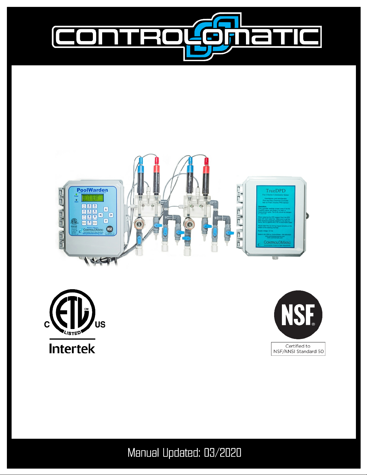
POOLWARDEN
Installation Manual
Including
PW-Plus and TrueDPD
Automated Pool & Spa Chemical Controller
And Data Recorder
ControlOMatic, Inc.
12659 Arbor Lane, Grass Valley, CA 95949
(530) 205-4520 • www.controlomatic.com • www.poolwardentraining.com
Manuals also available at:
https://www.controlomatic.com/support/documents

PoolWarden Manual • www.poolwardentraining.com • 530-205-4520 • 2
IMPORTANT WARNING AND SAFETY INSTRUCTIONS 3
POOLWARDEN OVERVIEW 5
PoolWarden Plus 5
SYSTEM COMPONENTS 5
Maximum Electrical Specifications 6
Environmental Specifications 6
Certifications 6
Models and Options 7
POOLWARDEN INSTALLATION 8
Mounting PoolWarden 8
Flow Cell To Circulation Plumbing 8
Sensor Wire Connection 11
Supply 110/240 Vac Input Selection 11
Load/Equipment Connection & Installation 12
Supported Auxiliary Dry Contact Loads/Equipment 13
POOLWARDEN PLUS - Option 14
TRUEDPD FREE CHLORINE SENSOR - Option 15
TrueDPD Replacement Parts 16
POOLWARDEN REPLACEMENT PARTS 17
Table of Contents
PoolWarden Manual • www.poolwardentraining.com • 530-205-4520 • 3
1 READ AND FOLLOW ALL INSTRUCTIONS
2 SAVE THESE INSTRUCTIONS
3 WARNING – To reduce the risk of injury, do not permit children to
use this product
4 DANGER – Risk of injury
4.1 Replace damaged cord immediately.
4.2 Do not bury cord.
4.3 Connect to a grounded, grounding type receptacle only.
4.4 Do not use an extension cord.
5 WARNING – This product is provided with a ground-fault circuit-
interrupter at the end of the power cord. The GFCI must be tested
before each use. Turn the PoolWarden off by placing the ON/OFF
switch to the OFF position. Next, push the test button on the GFCI
and place the ON/OFF switch to the ON position. The PoolWarden
should not operate. Now push the reset button on the GFCI and the
PoolWarden should now operate normally. When the product fails to
operate in this manner, there is a ground current flowing indicating
the possibility of an electric shock. Disconnect the power until the
fault has been identified and corrected.
6 It is very important to follow the safety guidelines in this manual to
ensure safe installation and programming. Safety of any system
incorporating this equipment is the responsibility of the assembler
of the system. Upon installation, it is important to properly train all
personnel basic water quality management techniques, proper
operation and programming to anyone who operates or services
PoolWarden.
7 All applicable local installation codes and ordinances must also be
adhered to. Improper installation will create an electrical hazard
which could result in death or serious injury to pool users, installers
or others due to electrical shock, and may also cause damage to
property. The PoolWarden must be installed by a licensed or
certified electrician or a qualified pool professional:
7.1 United States: National Electrical Code (NEC), NFPA 70
7.2 Canada: Canadian Electrical Code (CEC), CSA C22.1.
IMPORTANT WARNING AND SAFETY INSTRUCTIONS
PoolWarden Manual • www.poolwardentraining.com • 530-205-4520 • 4
8 WARNING – Disconnect all power to PoolWarden prior to any
service including the main AC power and any other AC sources that
may be connected to the AUX relays. Never apply power when
PoolWarden service door is unlocked or in the open position. Only
qualified and licensed technicians should perform any service or
repair.
9 WARNING – Do not install load bearing leads and/or sensor cables
longer than 3 meters.
10 WARNING – Always mount PoolWarden in safe and dry area. Never
mount PoolWarden above any other electrical equipment.
11 WARNING – Install PoolWarden in a location that is not accessible
to the public.
12 WARNING – Pool and Spa Chemical Safety
12.1 Never mix sodium hypochlorite and muratic acid!
12.2 When mixing acid and water, always add acid to the water,
never add water to the acid.
13 CAUTION – TEST THE GROUND FAULT CIRCUIT INTERRUPTER
BEFORE EACH USE OF THE POOL/SPA
14 CAUTION – CONNECT ONLY TO A CIRCUIT PROTECTED BY A
CLASS A GROUND FAULT CIRCUIT INTERRUPTER
15 Do not dispose in trash. Please visit www.controlomatic.com
for recycling information.
1 ATTENTION: TOUJOURS VÉRIFIER L’EFFICACITÉ DU
DISJONCTEUR DIFFÉRENTIEL AVANT D’UTILISER LE BAIN
2 ATTENTION: LIRE LA NOTICE TECHNIQUE
3 AVERTISSEMENT: DÉCONNECTER DU CIRCUIT D’ALIMENTATION
ÉLECTRIQUE AVANT L’ENTRETIEN
4 ATTENTION: CONNECTER UNIQUEMENT À UN CIRCUIT PROTÉGÉ
PAR UN DISJONCTEUR DIFFÉRENTIEL DE CLASSE A
IMPORTANT WARNING AND SAFETY INSTRUCTIONS

PoolWarden Manual • www.poolwardentraining.com • 530-205-4520 • 5
PoolWarden measures pH, sanitizer and temperature on up to two bodies of water and will control
the appropriate feed equipment to keep the measurements within a preprogrammed range. Using ORP
(oxidation reduction potential) technology the control of sanitizer takes into account the effects of pH, and
a pH lockout feature is also included for high pH values. Controls chemical feed equipment using relays to
keep the pool or spa water in balance. Water measurements are taken continuously while PoolWarden's
internal relay programing determines if chemical adjustments are needed. PoolWarden then
communicates the adjustment signals through relays which control the chemical feed equipment.
PoolWarden also contains additional dry-contact auxiliary relays that can be used to control
heaters, pumps, chlorine backup and external alarm notifications.
PoolWarden Plus
When adding the PW-Plus communication module, the software feature set will also be updated. Where
there are differences that will be pointed out.
System Components
tCONTROLLER: PoolWarden is a microprocessor based, modular automation system that is capable of
continuous monitoring locally onsite or remotely offsite.
tINTERFACE: PoolWarden uses a 16-button built in keypad, and an easy to read 80 character liquid crystal
display. The display’s internal back-light provides controller viewing in pool rooms with low light.
tMEMORY: PoolWarden is designed with nonvolatile memory which preserves all internal programming in case
of power loss. Internal memory is preserved for up to 10 years without having power applied.
tRELAYS: PoolWarden S (single pool) includes 4 relays (2 of which are dry contact relays). PoolWarden
D (two pools) includes 8 relays. Four of the 8 relays are dry contact relays (2 for each body of water).
tSENSORS: ORP, pH, Temperature, flow and optional free chlorine.
tVOLTAGE: Requires 120VAC input voltage in North America and 240VAC input voltage in Europe.
tSECURITY: PoolWarden is designed with a lockable enclosure and provides up to four levels of password
security protection (Admin, Tech, Service and Guest) for both local onsite and remote offsite interaction with the
controller.
tCOMMUNICATION: PoolWarden can connect to the Internet for direct monitoring, setup, and data interface by
adding the PW-Plus communication module which adds WIFI and Ethernet.
tDATA: PoolWarden will record up to 8192 lines of data with the built in internal memory. There is no limit when
adding the PW-Plus communication device
tHEATERS: Auxiliary relays can control pool heaters with up to two set-points for each day to facilitate
energy management.
tPUMP CONTROL: Auxiliary relays can be setup as a simple timer for controlling the on/off state of
main pumps.
tOVERFEED PROTECTION: PoolWarden is designed with 2 types of overfeed protection. Standard overfeed
limits the amount of time a relay can turn on feed equipment in a 24-Hour period.
tPROPORTIONAL/SPAN CONTROL: Proportionally reduces the on-time as the measurement gets closer to the
set-point to prevent overshoot.
tE-MAIL ALERTS: The data server provides support for 4 email addresses and 4 phone numbers for texts.
tAUXILIARY RELAYS: Auxiliary relays can control additional / backup sanitizer or acid feed pumps.
tPRINTING: Bluetooth printing when adding the PW-Plus communication module.
tSOFTWARE UPDATING: PW-Plus supports immediate software updating over the Internet.
PoolWarden Overview
PoolWarden Manual • www.poolwardentraining.com • 530-205-4520 • 6
Maximum Electrical Specifications
ITEM DESCRIPTION LIMIT
Input Voltage Maximum input AC voltage 240 VAC, 50-60 Hz
Input Current Maximum input current 10 A
Relay Voltage Maximum relay voltage 240 VAC
Relay Current Maximum Relay Current 2.5 A
Fuse Rating F1 5A, 250V, 05x20
Fuse Rating F2 5A, 250V, 05x20
Fuse Rating F3 1A, 250V, 05x20
Standby Current Maximum operating current 0.1 A Max
pH Measurement of pH 4.22 to 9.98
ORP Oxidation Reduction Potential 0 to 999 mV
Free Chlorine - PPM
With optional TrueDPD sensor NSF Certified Range
0 to 6.0 PPM 10%
Free Chlorine - PPM Extended non-NSF Certified Range 6.0 to 9.5 PPM 20%
Certifications
4010758
Conforms to
UL STD 1563
Certified to CSA STD
C22.2 No. 218.1
NSF/ANSI 50 - Equipment
for Swimming Pools, Spas,
Hot Tubs and Other
Recreational Water Facilities
http://info.nsf.org/Certified/Pools/Listi
ngs.asp?Company=C0214550&Stan
dard=050&
Environmental Specifications
ITEM DESCRIPTION LIMIT
Elevation Not to be used above 2000 m
Temperature Minimum/Maximum Operating Temperature 30/110 °F
Temperature Water temperature measurement. 32 to 122 °F
IP Rating Suitable for Outdoor Use IPX3
Pollution Pollution Degree 2
PoolWarden Manual • www.poolwardentraining.com • 530-205-4520 • 7
ITEM DESCRIPTION
PW-SMTD PoolWarden controller with flow cell and sensors, pre-mounted white backboard
PW-DMTD Adds second pool flow cell and sensors - 2 pool control
PW+SMTD Add PW-Plus communication module to PW-SMTD
PW+DMTD Add PW-Plus communication module to PW-DMTD
PW-SFAC PW-SMTD with single pool TrueDPD free chlorine sensor
PW-DFAC PW-DMTD with 2 pool TrueDPD free chlorine sensor
PW+SFAC Adds PW-Plus communication to PW-SFAC
PW+DFAC Adds PW-Plus communication to PW-DFAC
Models and Options

PoolWarden Manual • www.poolwardentraining.com • 530-205-4520 • 8
Mounting PoolWarden
Turn off any heaters, pool or spa circulation systems, chemical feed pumps or any related shut-off valves
or equipment and relieve pressure from the filtration system. Find a suitable mounting location near a
120/240 VAC power source that meets the following criteria:
tFacilitates a combined (influent & effluent) maximum tubing run of 30’.
tDo not mount controller above electrical sources or electrical equipment.
tAt least 10’ away from any pool, spa or body of water and not accessible to the public.
tAway from corrosive materials including fumes and physical hazards.
tNot in direct sunlight or directly above or near any heat source.
tFor 240 VAC, ability to hard wire with GFCI (ground fault circuit interrupter) protection.
Securely mount controller, or the optional controller backboard, vertically on the wall using supplied
screws or appropriate fasteners for the wall construction. Product shall be positioned such that the power
supply cord plug, which is the disconnect device, can be easily accessible.
Flow Cell To Circulation Plumbing
There are many ways to connect the flow cell tubing to the circulation plumbing. Always make sure the
input source to the flow cell is well upstream from any chemical injection points. Successful flow cell
installation requires a pressure differential, or there will be no water flowing through the cell. The Flow
cell input should be filtered water and therefore after the filter. Never install the input to the flow cell
between the main circulation pump and filter as that will be very high pressure which may damage the
sensors and provide the most debris to the flow cell. PoolWarden is equipped with a strainer to filter out
any debris that does get past the filter. Periodically check and clean the strainer. Install the flow cell
return after the heater, there will be a pressure drop across that should be sufficient to provide flow
through the flow cell. If there is no heater, the next choice is the suction plug in the pumps strainer, make
sure to adjust the return valve on the flow cell to keep the pressure in the flow cell positive.
tFlow Cell Input: Drill & tap a connection point in the circulation system at a location just after the filter.
The best location is where there is a pipe fitting as that will provide the most threads. Install a tube
connector and run tubing to the input side of the flow cell.
tFlow Cell Output: Drill & tap a connection point in the circulation system at a location with reduced
pressure just after the heater. Install a tube connector and run tubing to the return side of the flow
cell.
CAUTION: Maximum pressure across the sensors should be 10 PSI (pressure gauge may be required).
Always expose the sensors to positive pressure. Prevent exposing the sensors to suction or a vacuum
by connecting the flow cell output tubing to the suction side of the pump as the vacuum may suck the
sensor gel from the sensors rendering the sensors inoperable in a very short period of time.
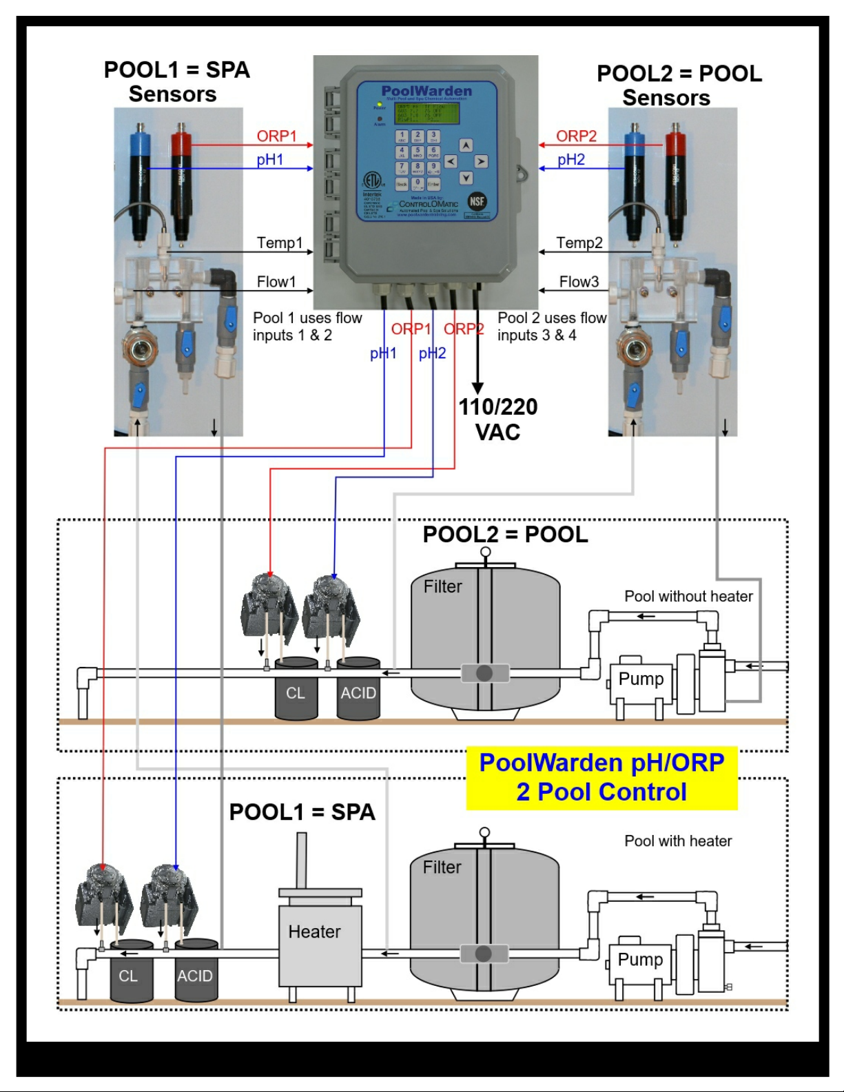
tIf not pre-mounted, find a suitable location to mount the acrylic flow cell within 3 feet of the controller.
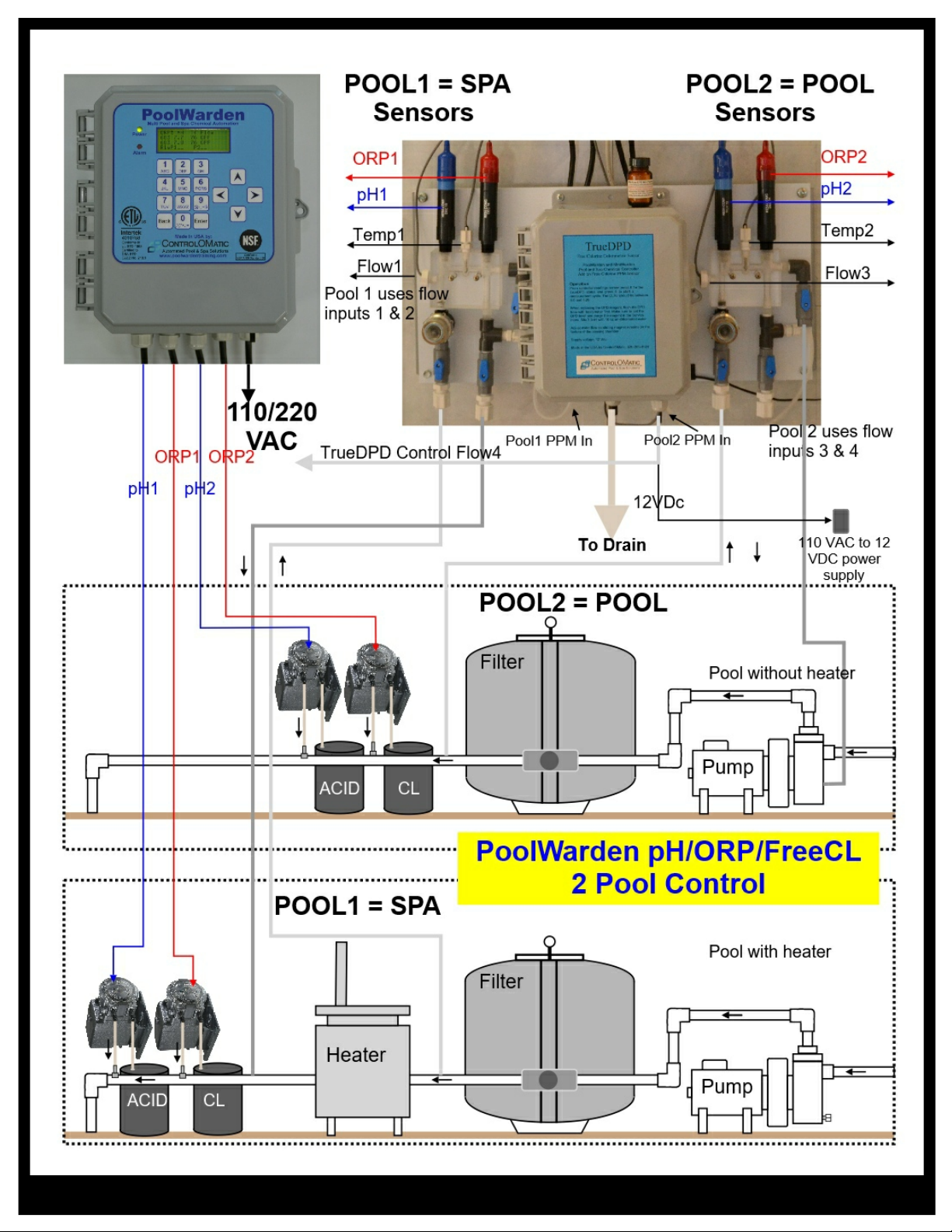
Mount and assemble flow cell parts according to the following figures. If the TrueDPD is being
installed there will be a few additional fittings for the flow cell to connect to the TrueDPD inlet.
Remove pH (Blue) and ORP (Red) sensors from the boxes. Use Teflon tape on sensor threads and
all other flow cell parts to ensure water tight connection and fasten accordingly. REMOVE THE
SENSOR GUARDS FROM THE SENSORS!
tInstall the appropriate 1/2” or 3/8” hard vinyl input and output tubing from the pools circulation system
connection points to the “In” and “Out” connection points on the flow cell.
tOnce connected, turn circulating pump back on, test for leaks at all connection points, and make sure
all air evacuates form the tubing.
PPPoolWarden Installation
PoolWarden Manual • www.poolwardentraining.com • 530-205-4520 • 9
PoolWarden Manual • www.poolwardentraining.com • 530-205-4520 • 10
Questo manuale è adatto per i seguenti modelli
1
Indice
Altri manuali ControlOMatic Sistema di filtraggio dell'acqua

ControlOMatic
ControlOMatic TechniChlor Manuale utente

ControlOMatic
ControlOMatic MegaChlor Manuale utente

ControlOMatic
ControlOMatic MegaChlor Manuale utente

ControlOMatic
ControlOMatic MegaChlor Manuale utente

ControlOMatic
ControlOMatic MegaChlor Manuale utente

ControlOMatic
ControlOMatic CHLOR MAKER 10 Manuale utente

ControlOMatic
ControlOMatic ChlorMaker Manuale utente


