CYP CPLUS-442CVEA Manuale utente

CPLUS-442CVEA
4×6 HDMI and HDBaseT Matrix
with Audio Matrixing & LAN Serving
Operation Manual
Operation Manual


DISCLAIMERS
The information in this manual has been carefully checked and
is believed to be accurate. Cypress Technology assumes no
responsibility for any infringements of patents or other rights of third
parties which may result from its use.
Cypress Technology assumes no responsibility for any inaccuracies
that may be contained in this document. Cypress also makes no
commitment to update or to keep current the information contained
in this document.
Cypress Technology reserves the right to make improvements to this
document and/or product at any time and without notice.
COPYRIGHT NOTICE
No part of this document may be reproduced, transmitted,
transcribed, stored in a retrieval system, or any of its part translated
into any language or computer le, in any form or by any means—
electronic, mechanical, magnetic, optical, chemical, manual, or
otherwise—without express written permission and consent from
Cypress Technology.
© Copyright 2017 by Cypress Technology.
All Rights Reserved.
TRADEMARK ACKNOWLEDGMENTS
All products or service names mentioned in this document may be
trademarks of the companies with which they are associated.

SAFETY PRECAUTIONS
Please read all instructions before attempting to unpack, install or
operate this equipment and before connecting the power supply.
Please keep the following in mind as you unpack and install this
equipment:
• Always follow basic safety precautions to reduce the risk of re,
electrical shock and injury to persons.
• To prevent re or shock hazard, do not expose the unit to rain,
moisture or install this product near water.
• Never spill liquid of any kind on or into this product.
• Never push an object of any kind into this product through any
openings or empty slots in the unit, as you may damage parts
inside the unit.
• Do not attach the power supply cabling to building surfaces.
• Use only the supplied power supply unit (PSU). Do not use the PSU
if it is damaged.
• Do not allow anything to rest on the power cabling or allow any
weight to be placed upon it or any person walk on it.
• To protect the unit from overheating, do not block any vents or
openings in the unit housing that provide ventilation and allow for
sufcient space for air to circulate around the unit.
REVISION HISTORY
VERSION NO. DATE (DD/MM/YY) SUMMARY OF CHANGE
RDV1 16/03/17 Preliminary release
RDV2 18/04/17 Corrections to section 6.4

CONTENTS
1. Introduction......................................................1
2. Applications.....................................................1
3. Package Contents ..........................................2
4. System Requirements......................................2
5. Features............................................................2
6. Operation Controls and Functions.................4
6.1 Front Panel ................................................. 4
6.2 Rear Panel.................................................. 5
6.3 Side Panel .................................................. 7
6.4 Remote Control......................................... 8
6.5 OLED Menu ................................................ 9
6.6 IR Cable Pin Assignment......................... 10
6.7 RS-232 Protocol........................................ 10
6.8 RS-232 and Telnet Commands .............. 11
6.8.1 Command Syntax.......................... 11
6.8.2 Real World Command Use ........... 13
6.8.3 Full Command List.......................... 16
6.9 Telnet Control .......................................... 30
6.10 WebGUI Control .................................... 32
6.10.1 Video Switch................................. 34
6.10.2 Zone Audio ................................... 37
6.10.3 Extended Audio ........................... 38
6.10.4 HDMI Audio................................... 39
6.10.5 HDBaseT Audio............................. 40
6.10.6 Zone A/V Pairing .......................... 41
6.10.7 EDID Settings................................. 42
6.10.8 HDBaseT & H/W Info..................... 44
6.10.9 User Cong ................................... 45
6.10.10 System Settings........................... 45
6.10.11 Logout ......................................... 46

7. Connection Diagram ....................................47
8. Specications ................................................48
8.1 Technical Specications ........................ 48
8.2 Video Specications............................... 49
8.2.1 Supported HDMI Resolutions ........ 49
8.2.2 Maximum HDMI Cable Length..... 50
8.3 Audio Specications............................... 50
8.3.1 Analog Audio ................................. 50
8.3.2 Linear PCM Audio .......................... 51
8.3.3 Compressed Audio........................ 51
8.3.4 Audio Adjustments......................... 51
8.4 Category Cable Specications............. 52
8.5 HDBaseT Features.................................... 52
9. Acronyms .......................................................53

1
1. INTRODUCTION
This 4×6 HDMI and HDBaseT Matrix supports routing and transmission of
video (resolutions up to 4K@60Hz w/ HDMI 2.0 & HDCP 2.2) and audio
(multi-channel digital/stereo analog) while providing exible control
via IR, RS-232, Telnet or WebGUI. As many as four UltraHD sources may
be routed to any of six destinations, four via single Cat.5e/6/7 cables
(up to 100m at 1080p or up to 60m at 4K@30Hz) and two via HDMI
2.0 outputs. The two HDMI 2.0 outputs support transmission of 18Gbps
UltraHD HDMI sources (up to 4K@60Hz, 4:4:4) from any HDMI input or
they can mirror any of the HDBaseT outputs for local monitoring. 3D
video is also supported when compatible sources and displays are
connected.
This product supports passing 7.1 channel LPCM digital audio as well
as advanced bitstream and HD bitstream audio formats. Additionally,
four analog audio outputs are available to provide stereo breakout
audio from the associated HDBaseT output (LPCM 2.0 sources
only). Beyond basic video routing, this product also incorporates
an independent audio matrix with six audio outputs and four audio
inputs. Offering discrete audio routing, insertion and extraction, this
product makes it possible to have multiple audio zones within your
installation. This product supports the Optical Audio Return (OAR)
channel feature, found on compatible HDBaseT receivers, allowing
optical audio sources connected to those receivers to be sent back
to the matrix unit.
LAN support allows your 100BaseT network to be extended to smart TVs
or game consoles. The Power over HDBaseT (PoH) function can power
compatible receivers, providing greater exibility in your installations.
Control is via manual selection buttons, WebGUI, Telnet, RS-232 or IR
remote.
2. APPLICATIONS
• Full audio/video matrix systems
• Residential AV matrix installations
• Commercial AV matrix installations
• Security systems
• University lecture hall systems
• Retail installation systems

2
3. PACKAGE CONTENTS
• 1× 4 by 6 HDMI and HDBaseT Matrix with Audio Matrixing
• 1× Remote Control (CR-163)
• 2× IR Extender Cable
• 2× IR Blaster Cable
• 1× 24V/6.25A DC Power Adaptor
• 1× Power Cord
• 1× Rack Ear Set
• 1× Operation Manual
4. SYSTEM REQUIREMENTS
• HDMI or DVI source equipment such as media players, video game
consoles, set-top boxes, PCs or laptops. DVI equipped source
devices must be connected via DVI to HDMI cables/adapters
• HDMI receiving equipment such as HDTVs, monitors or audio
ampliers
• The use of industry standard Cat.6, Cat.6a or Cat.7 cable is highly
recommended
• HDBaseT™ receivers equipped with Optical Audio Return (OAR)
channel support are strongly recommended
• The use of “Premium High Speed HDMI” cables is highly
recommended
5. FEATURES
• HDMI 2.0, HDCP 1.4 and HDCP 2.2 compliant
• Routes 4 HDMI sources to 6 displays using 4 HDBaseT outputs and 2
independent or mirrored HDMI outputs
• HDBaseT 5-Play™ convergence: High-Denition video and audio,
100BaseT Ethernet, 48v PoH (Power over HDBaseT) and control (Bi-
directional IR & RS-232 pass through)
• Supported HDBaseT resolutions: VGA~WUXGA, 480i~1080p,
4K@24/25/30Hz (RGB, YUV 4:4:4 & YUV 4:2:2) & 4K@60Hz (YUV 4:2:0)
dependent upon the output display’s EDID settings

3
• Supports HDMI output resolutions up to 4K@60Hz (RGB/YUV 4:4:4)
• Supports automatic 4K@60Hz RGB/YUV 4:4:4 to YUV 4:2:0 conversion
for HDBaseT outputs
• 4K@30Hz signals can be transmitted up to 60m via Cat.5e/6 and up
to 100m via Cat.6a/7
• Supports pass-through of all standard digital audio formats: LPCM
2.0/5.1/7.1, bitstream, and HD bitstream
• Supports audio matrix functionality enabling full audio management
of the system including HDBaseT audio selection, fully independent
audio-only zones and HDMI audio embedding and de-embedding
(LPCM only)
• Supports Digital to Analog Conversion (DAC) and Analog to Digital
Conversion (ADC) for audio integration
• Supports volume, treble, bass, and audio delay for lip-sync (up to
230ms) on analog audio outputs and mute on all outputs
• HDBaseT outputs with Optical Audio Return (OAR) support
• Advanced internal and external EDID management with 4 sets of
congurable EDID settings
• Bi-directional IR support over HDBaseT
• Control via front panel controls, Ethernet (Telnet & WebGUI), RS-232,
& IR remote
• 1U rack mounted design
4
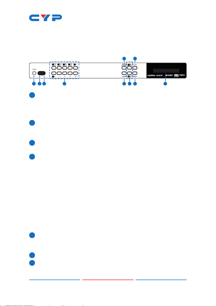
6. OPERATION CONTROLS AND FUNCTIONS
6.1 Front Panel
2.2
isolated
+
21 3 6 7 8
5 9
104
1POWER: Press this button to power the unit on or place it into stand-
by mode.
Note: Network functionality and PoH (if the second power supply is
connected) remain active when the unit is in stand-by mode.
2POWER LED: This LED will illuminate GREEN to indicate the unit is on
and receiving power. When the unit is in stand-by mode the LED
will illuminate RED.
3IR WINDOW: Accepts IR signals from the included IR remote for
control of this unit only.
4OUTPUT A~F & INPUT/NUMBER 1~4: Press the “OUT” button to enter
output selection mode. Next, press the output keys (A~F) of the
outputs you wish to route a source to (they will ash to indicate
selection). Next, press the “IN” key followed by the input (1~4)
you wish to route to the selected outputs. Finally, press “ENTER” to
conrm your selection and execute the routing change.
For example, if you wish to display input 1 on outputs A~D then the
following sequence of button presses should be performed: OUT →
A, B, C, D → IN → 1 → ENTER
When directly entering Ethernet address information into the unit
all 10 buttons are used to represent the numbers from 0 to 9 (button
10 = 0) to make number entry more streamlined.
5MENU/CANCEL: Press the “MENU/CANCEL” button to enter the
OLED menu, or to back out from menu items. For a description of
the menu tree, please refer to section 6.5.
6ENTER: Press this button to conrm selections.
7+/IN: Within the menu, this button moves you up within the menu
tree. Otherwise, in routing mode, this button allows you to make
Indice
Altri manuali CYP Commutatore a matrice

CYP
CYP PUV-662PL-4K22 Manuale utente

CYP
CYP CMIR-882 Manuale utente

CYP
CYP PUV-44XPL-4K22-KIT Manuale utente

CYP
CYP PU-424HBTL-KIT Manuale utente

CYP
CYP OR-HD24S Manuale utente

CYP
CYP OR-IR44 Manuale utente

CYP
CYP nT15GX01 Manuale utente

CYP
CYP CDPS-44SM Manuale utente

CYP
CYP CPLUS-662CVAL Manuale utente

CYP
CYP OR-44-4K22 Manuale utente

CYP
CYP CMPRO-U4H4CVPL Manuale utente

CYP
CYP PUV-44XPL-AVLC Manuale utente

CYP
CYP EL-42M-PIP Manuale utente

CYP
CYP CPLUS-V4H2HA Manuale utente

CYP
CYP PUV-442-4K22 Manuale utente

CYP
CYP CMSI-88 Manuale utente

CYP
CYP CMSI-4H4CV Manuale utente

CYP
CYP SM-2X2-HDMI-LC Manuale utente

CYP
CYP CDPS-44SM Manuale utente

CYP
CYP CMPRO-U4H4CVE Manuale utente


