DanVex AD-200 Manuale utente

Manual
Desiccant dehumidifiers
AD-200 / AD-400 / AD-550
rev. 2.01

1www.danvex.
SAVE THIS MANUAL FOR FUTURE REFERENCE
CONTENT
Introduction ............................................................................................................................................................3
Purpose .............................................................................................................................................................3
Content .............................................................................................................................................................3
Copyright .........................................................................................................................................................3
1.
SAFETY AND APPLICATION .........................................................................................................................4
1.1 Safety of use ............................................................................................................................................4
1.2 Applications .............................................................................................................................................5
2 DEVICE INFORMATION ..................................................................................................................................6
2.1 Standards ..................................................................................................................................................6
2.2 How it works ............................................................................................................................................6
2.3 Construction ............................................................................................................................................7
2.3.1 Enclosure ................................................................................................................................................7
2.3.2 Conveying air circuit ..........................................................................................................................7
2.3.3 Regeneration air circuit .....................................................................................................................7
2.3.4 Rotor ........................................................................................................................................................7
2.3.5 Rotor drive .............................................................................................................................................7
2.3.6 Safety devices .......................................................................................................................................7
3 INSTALLATION .................................................................................................................................................8
3.1 Introduction ..............................................................................................................................................8
3.2 Transport and storage ...........................................................................................................................8
3.3 Checking before installation ...............................................................................................................8
3.4 Moving ........................................................................................................................................................8
3.5 Place of installation and its arrangement ......................................................................................8
3.6 Support/ Foundation .............................................................................................................................8
3.7 Connecting to air ducts .........................................................................................................................8
3.8 Electrical connection .............................................................................................................................12
3.9 Connecting external humidity sensors ...........................................................................................12
3.10 Checking before starting ...................................................................................................................13

2www.danvex.
4 OPERATION .....................................................................................................................................................13
4.1 Elements of the control and monitoring panel ..........................................................................13
4.2 Humidity controller interface and settings ..................................................................................14
4.3 Algorithm of operation of the dryer components .....................................................................16
5 MAINTENANCE ................................................................................................................................................17
5.1 Introduction .............................................................................................................................................17
5.2 Filters ..........................................................................................................................................................17
5.3 Rotor ...........................................................................................................................................................17
5.4 Gear motor ...............................................................................................................................................17
5.5 Heating device .......................................................................................................................................17
5.6 Drive belt .................................................................................................................................................17
6 TROUBLESHOOTING ....................................................................................................................................18
6.1 Inspection and maintenance intervals .........................................................................................18
6.2 Troubleshooting ...................................................................................................................................19
7 CHARACTERISTICS ......................................................................................................................................20
8 OVERALL AND MOUNTING DIMENSIONS .........................................................................................21
9 ELECTRICAL WIRING DIAGRAM .............................................................................................................23

3www.danvex.
Introduction
Purpose
This user manual contains complete information about the dehumidifier model you have
purchased, including details of its design, principle of operation, installation and operation
instructions.
Content
General information about the management of the dehumidification process, the principle
of operation and maintenance standards, system errors, diagnostics and troubleshooting.
Copyright
We reserve all rights to update and clarify the information contained in this manual.
Desiccant dehumidifiers
AD-200 / AD-400 / AD-550
Manufactured by DanVex (Finland)
www.danvex.fi

4www.danvex.
Warning!!!
All electrical connections must be carried out by local specialists in accordance with current
standards, otherwise there is a risk of death, injury, equipment damage and property damage!
Before starting work on electrical equipment, read this manual in order to avoid errors,
which could result in death or equipment damage
1 SAFETY ANDAPPLICATION
1.1 Safety of use
All models of dehumidifiers in this series are manufactured in compliance with the requirements
of European safety standards and current regulations; the requirements for the safety of the operator
and equipment were taken into account during design and production. Each section of this manual
provides safety information and describes in detail the circumstances that can lead to abnormal
situations. Such information is marked with a warning label "dangerous".
This manual also provides complete information on how to maintain the dehumidifier.
It is for guidance only and does not remove the operator's responsibility for compliance
with personal safety requirements at work and local safety standards.
During the installation and operation of equipment,
each employee must follow the instructions below:
•follow the descriptions and instructions in this manual to ensure the protection
of the equipment;
•ensure the safety of yourself and others;
•the unit must be operated and maintained by professional technicians;
•electrical components must be serviced by authorized electricians;
•it is forbidden to install the dehumidifier in rooms equipped with explosion-proof devices;
•before opening any service panel, disconnect the device from the main power supply;
•the device must be cooled down for at least 15 minutes before maintenance;
•if no maintenance is being performed, the maintenance panel must be closed;
•the unit can only dehumidify at atmospheric pressure;
•do not use the unit without a filter; if the filter is not installed, the rotor will become dirty
and stop working;
•it is forbidden to remove warning signs on the device;
•this manual must be kept with care;
•original spare parts must be used;
•written permission must be obtained for any adjustments or modifications.

5www.danvex.
1.2 Applications
The AD series dehumidifiers use a silica-gel coated composite adsorption rotor and are capable
of effectively dehumidifying air at atmospheric pressure in a relative humidity range of 2 to 100%
and an operating temperature range of -20°C to +50°C.
Adsorption dryers are widely used in the following areas:
•rooms and areas with low temperatures and low humidity;
•areas with relative humidity below 35% and low dew point;
•process air preparation systems;
•single pass airflow systems;
•manufacturing, packaging, storage, testing and research of pharmaceutical
products;
•production and packaging of confectionery and food products;
•pneumatic conveying of powder materials;
•production of electronics;
•archival repositories of photographic materials and films;
•refrigerated warehouses;
•seed storages;
•"clean" rooms;
•pumping stations;
•injection molding production areas;
•ice areas;
•drying of tanks and ship holds;
•conservation of turbines in the prevention of corrosion at power plants
•and etc.

6www.danvex.
2 DEVICE INFORMATION
2.1 Standards
The design of the dehumidifier complies with protection class IP 44, IEC standard.
2.2 How it works
The main component of the installation is a honeycomb rotor, consisting of a special ceramic
fiber and active silica gel. The two sides of the rotor are separated by special hermetic seals into
two zones: the working zone, which is 3/4 of the rotor surface, and the regeneration zone, 1/4
of the rotor surface. When moist working air passes through the filter into the rotor, the moisture
from the air is absorbed by the dehumidifying working sector of the rotor, and the dehumidified
air is expelled from the other side of the rotor by the fan. At the same time, the regeneration air
passes through the filter, heats up and enters the regeneration sector of the rotor. In this zone,
the heated regeneration air removes from the rotor the moisture previously adsorbed
by the silica gel, which is then removed in the form of steam from the dryer and into the street.
Schematic diagram of the operation of an adsorption dryer
Note:
the diagram does not show the obligatory filters for working and regeneration air

7www.danvex.
2.3 Construction
2.3.1 Hull
•compact stainless steel frame construction for corrosion resistance and effective insulation
against condensation;
•removable panels providing access to internal components;
•well-designed layout and selection of units to ensure minimum head drop.
2.3.2 Conveying air circuit
•at the air inlet there is a filter class G3 with the possibility of cleaning;
•centrifugal high efficiency low noise fan.
2.3.3 Regeneration air circuit
•at the air inlet there is a filter class G3 with the possibility of cleaning;
•centrifugal, high-efficiency, low-noise, forward-curved fan.
•heating section using PTC heaters.
2.3.4 Rotor
•The rotor is the main part of the dryer. Its characteristics directly affect the performance
and operation of the dehumidifier. The rotor is made of a special heat- resistant composite
material. The composite material is a corrugated structure filled with a highly effective
desiccant, forming many small air flow channels, contacting the air with a large area
and increasing the dehumidification efficiency.
2.3.5 Rotor drive
•Rotation of the rotor at the desired speed can be achieved using an electric motor
with a geared motor and a belt drive. The belt is located on the outer rim of the rotor
and is driven by a geared motor pulley.
•The belt tensioner maintains proper belt tension to prevent belt slip page. The direction
of rotation of the rotor and the condition of the belt need to be checked regularly.
2.3.6 Safety devices
•Motor protection against overload and short circuit: fan motors for working and regeneration
air, rotor drive motor have overload and short circuit protection functions.
•Shutdown protection: When the dryer is switched off under normal conditions,
the regeneration fan continues to run until the regeneration heater and rotor have cooled
below 60°С.

8www.danvex.
3 Installation
3.1 Introduction
The information in this chapter describes the work required to install the device.
Careful familiarization before installation will help you properly organize the installation work.
3.2 Transport and storage
To guarantee the quality and reliability of each dryer, we test all devices at the factory.
If the dryer is in storage:
•keep the original packaging;
•avoid physical damage to the equipment;
•store the dehumidifier indoors, protect it from dust, moisture and frost.
3.3 Check before installation
Remove the packaging and check the equipment: if damage is found, contact the supplier/
manufacturer.
3.4 Moving
Before starting loading and unloading, check the weight of the equipment. It is recommended
to use lifting devices (stacker or forklift) to move the equipment. Please note that the dryer must
only be lifted properly to avoid tipping over and damage.
3.5 Place of installation and its arrangement
The dehumidifier is designed for indoor and outdoor use. To ensure proper maintenance for
opening the service panels, it is recommended that when installing the dryer, leave a free space
on all sides of about 800 mm.
The minimum width of the service space must not be less than the width of the dryer.
The unit cannot be placed in an explosive place, and also cannot work with air containing
explosive substances.
For outdoor installation, measures must be taken to protect against rain, snow, dust
3.6 Support/ foundation
The dehumidifier should be installed in a horizontal position on a level ground or platform.
The installation location must have sufficient bearing capacity to support the weight of the
installation. It is recommended to fix the dehumidifier to the base. Use a building level during
installation.
3.7 Duct connection
The dimensions of the process and regeneration air ducts must comply with the recommendations
of the ISO7807 standard. The air ducts are connected using an appropriate flange, while the bolt
diameter should not exceed 20 mm. When connecting to the duct, consider the following factors:
•to reduce static pressure losses and not reduce dehumidification performance, shorten
the length of the air ducts if possible;
9www.danvex.
•to guarantee the high performance of the dryer, all rigid (galvanized) duct flanges must
be air tight;
•the air duct must have good thermal insulation to protect the inner metal part of the air
duct from condensation and hence from corrosion;
•to reduce the level of noise and vibration from the air passing through the duct, use
strong and soft, air tight adapters;
•the air duct leading directly to the dryer must be fully anchored to reduce stress
and pressure on the flanges from the weight of the duct.
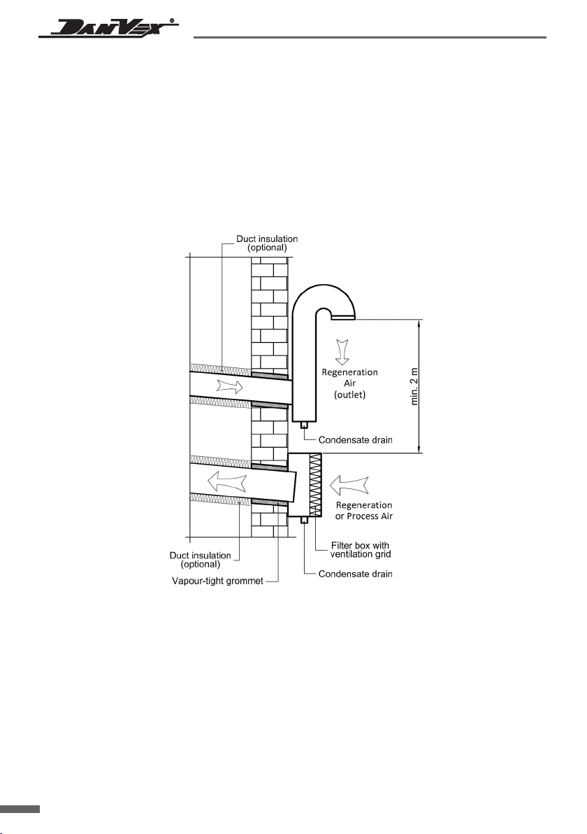
If air is taken into the dehumidifier from outside, the air inlet must be sufficiently high above
the ground or equipped with an additional inlet filter to prevent dust and debris from being
sucked in. The inlet must be away from possible sources of pollution such as exhaust gases,
steam and harmful gases.
To prevent humid air at the outlet from humidifying the process air at the inlet, it is necessary
to separate the inlet of external process air at a distance of at least 2 m from the humid air outlet.
The design of the duct must prevent the penetration of rain and snow.
The regeneration outlet air is hot and humid. Condensation from it can easily form on the inside
wall of the duct, so the duct must be laid with a downward slope away from the unit. In addition,
a condensate drain hole with a diameter of 10 mm must be installed at the lowest point of the
duct to prevent accumulation and stagnation of water.
Altri manuali per AD-200
1
Questo manuale è adatto per i seguenti modelli
2
Indice
Altri manuali DanVex Deumidificatore

DanVex
DanVex DEH-290h Manuale utente

DanVex
DanVex AD-3000 Manuale utente

DanVex
DanVex AD-550 Manuale utente

DanVex
DanVex AD-400 Manuale utente

DanVex
DanVex DEH-900i Manuale utente

DanVex
DanVex AD-200 Manuale utente

DanVex
DanVex DD Series Manuale utente

DanVex
DanVex DEH-1600i Manuale utente

DanVex
DanVex DEH-600wp Manuale utente

DanVex
DanVex DEH-1200P Manuale utente


