Dini Argeo DGT100 Manuale utente
A
I
R
B
R
E
A
T
H
I
N
G
www.diniargeo.com
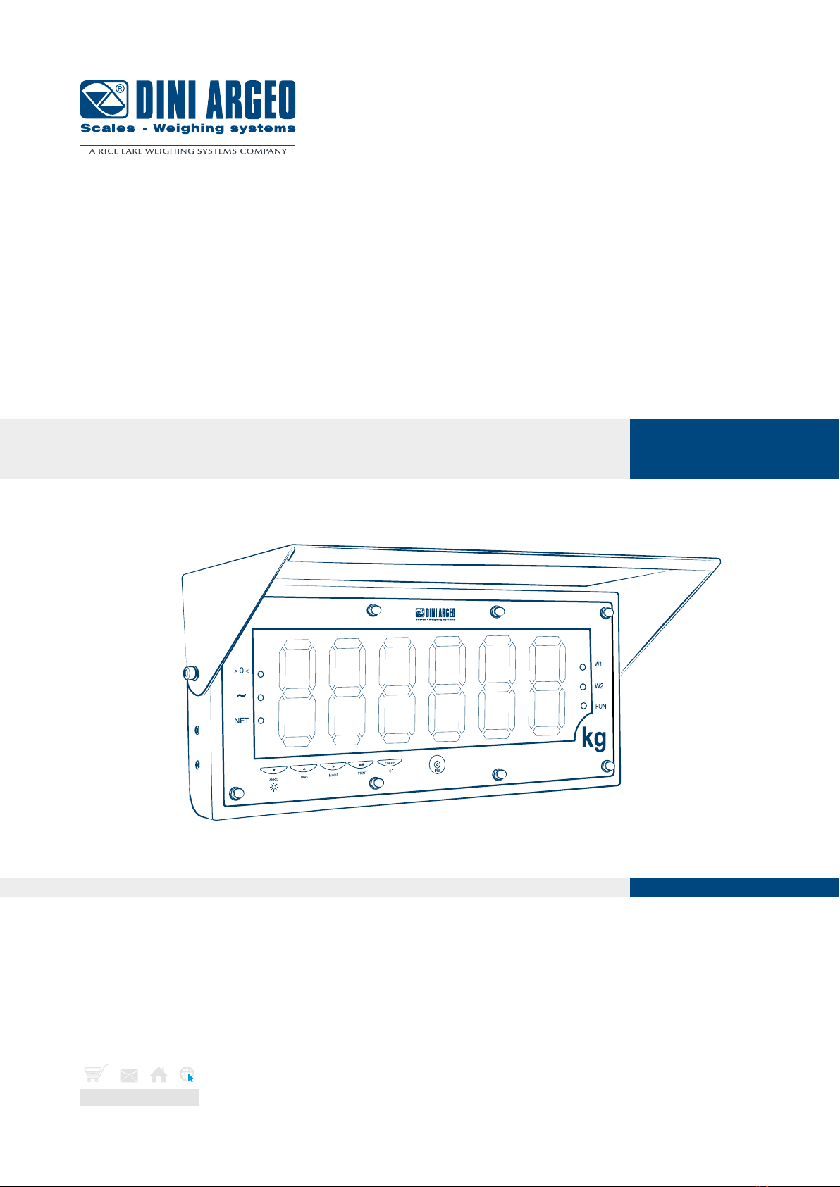
DGT100
Digital weight indicator with 4 channels
ENGLISHUSER MANUAL
For DGT100BC, DGT100AN and DGT100PB with firmware release minimum 08.03

3
Optimized layout for A4 print.
USER_MAN_ENG_DGT100_V8
Contents
Introduction 7
Transmitter installation 8
Installation requirements 8
Electrical precautions 9
Earthing of the system 11
Technical features 14
Load cell installation 15
Wiring diagrams 16
DGT100 16
DGT100AN 17
DGT100PB 18
Display and function of the keys 19
Advanced programming menu 20
Access to the menu and saving the changes 20
Function of the keys in the menu 20
Block diagram of the menu 21
Mode of use of the DGT100 23
On / Off 24
Theoretical calibration 25
Dependent channels 25
Independent channels / transm 26
Calibration with sample weights 27
Dependent channels (with digital equalisation) 27
Independent channels / transm 29
Equalisation 31
Manual calibration 32
Manual calibration 32
Quick zero calibration (pre-tare zeroing) 32
4
Optimized layout for A4 print.
USER_MAN_ENG_DGT100_V8
Filter and stability 33
Filter adjustment 33
Stability detection sensitivity 33
Display updating frequency 34
Gravity 34
Zeroing parameters 35
Auto-zeroing on ignition 35
Maximum percentage of manual zeroing 35
Zero tracking 35
Restoring zero 36
Semi-automatic zeroing 36
Tare functions and parameters 37
Tare mode 37
Semi-automatic tare 37
Predetermined tare 37
Clearing the tare 37
Alibi memory 38
Enabling the alibi memory 38
Saving a weighing operation in the alibi memory 38
Reading the alibi memory 39
Initialising the alibi memory 39
Use functions 40
High resolution 40
Peak detection 40
Converting units of measurement 40
Alibi memory 40
No function 40
Input configuration 41
Output configuration 42
Analog output configuration 43
Serial communication configuration 45
Selection of the PC serial port 45
Configuration of the printer port (COM.PRN) 46

5
Optimized layout for A4 print.
USER_MAN_ENG_DGT100_V8
Transmission mode 46
Baud rate, parity, data bits, stop bits 47
Printer power on mode 47
CTS signal 47
Print language 47
Reactivation of printing 48
Configuration of the PC port (COM.PC) 48
Transmission mode 48
Baud rate, parity, data bits, stop bits 49
Communication protocols 50
Standard string 50
Extended string 50
Multi-scale string 51
Serial commands 52
Diagnostics 55
Cells / converter test 55
Firmware release 55
Serial number 55
Display 55
Keypad 55
Serial ports 56
CTS signal 56
Inputs 56
Outputs 56
Analog output 56
Programming the Setpoints 56
Restoring factory settings 57
Date and time setting 57
Screen saver 58
Backlight intensity 58
Remote control configuration 59
Auto switch-off 59
Alarms 60

6
Optimized layout for A4 print.
USER_MAN_ENG_DGT100_V8

7
Optimized layout for A4 print.
USER_MAN_ENG_DGT100_V8
Dear Customer,
Thank you for purchasing a DINI ARGEO product.
This manual contains all the instructions for a correct installation and commissioning of the DGT100 4-channel digital weight indicator.
While thanking you for purchasing this product, we would like to draw your attention to some aspects of this manual.
This booklet provides useful information for the correct operation and maintenance of the scale to which it refers; it is therefore essential
to pay the greatest attention to all those paragraphs that illustrate the simplest and safest way to operate.
It is recommended that you carefully follow the instructions for programming the weight indicator; performing actions not indicated in this
manual could compromise the proper functioning of the scale.
The utmost care has been taken in compiling this manual, but reports of any inaccuracies are always welcome.
The instrument is covered by warranty and MUST NOT BE TAMPERED WITH BY THE USER under any circumstances.
Any attempt at repair or modification may expose the user to the danger of electric shock and voids any warranty conditions, relieving
the Manufacturer from all liability.
Any problem with the product must be reported to the manufacturer or to the retailer where it was purchased.
In any case, always TURN OFF THE POWER SUPPLY before any installation or repair operation.
Introduction

8
Optimized layout for A4 print.
USER_MAN_ENG_DGT100_V8
Transmitter installation
Installation requirements
Observe the following conditions for correct installation of the indicator and of the load receiver:
• Flat, level support surface.
• Stability and absence of vibrations.
• Absence of aggressive dusts and vapours.
• Absence of draughts.
• Make sure that the platform is levelled or that the load cells are evenly supported.
• Moderate temperature and humidity (15°C - 30°C and 40% - 70%).
• Do not install in an environment where there is a risk of explosion.
• All indicator connections must be made in accordance with applicable regulations in the area and environment of installation. Ob-
serve the electrical precautions listed in the section “Electrical precautions”.
• Ensure that it is correctly earthed, see the relevant section “Earthing of the system”.
• Do not perform welding when the load cells have already been installed.
• If necessary, use watertight sheaths and fittings to protect the load cell cables.
• Any junction boxes must be watertight.
• Anything not expressly described in this manual constitutes improper use of the equipment.

9
Optimized layout for A4 print.
USER_MAN_ENG_DGT100_V8
Electrical precautions
• Use a regulated mains supply within ± 10% of the rated voltage.
• The electrical protections (fuses, etc.) are the responsibility of the installer.
• Observe the recommended minimum distances between cables of dierent categories (see table on page 10).
• The following cables must comply with the maximum permissible lengths (see table on page 10), they must be shielded and must
beinserted alone in metal conduits or pipes:
- the load cell extension cables;
- the signal amplifier cables;
- the cables for connecting the serial ports;
- the analog output cables.
• The cell or amplifier cables must have an independent input in the electrical panel. They must be connected (if possible) directly to
the terminal block of the indicator without passing through the conduit with other cables.
• Fit “RC” filters:
- on the contactor coils;
- on the solenoid valve coils;
- on all devices that produce electrical interference.
• If condensation can occur inside the weight indicator, it is advisable to keep the equipment powered at all times.
• Connections to load cells and any external device must be as short as possible.
• The cable ends (connectors, leads, terminals, etc.) must be installed correctly; the cable shielding must be kept intact until close to
the connection point.
• If the indicator is placed inside an electrical panel, a shielded cable must also be used for the power supply.

10
Optimized layout for A4 print.
USER_MAN_ENG_DGT100_V8
Category I Category II Category III Category IV
Distance
≥ 100 mm
≥ 200 mm
≥ 500 mm
≥ 100 mm
≥ 500 mm
≥ 500 mm
Classification
Fieldbus, LAN network
(PROFIBUS, Ethernet,
Devicenet...).
Shielded data cables
(RS232...).
Shielded cables for
analog digital signals
< 25 V (sensors, load
cells...).
Low voltage power sup-
ply cables (< 60 V).
Coaxial cables.
DC supply cables with
voltage > 60 V and <
400 V.
AC supply cables with
voltage > 25 V and <
400 V.
Power supply cables
with voltage > 400 V.
Telephone cables.
Any cable subject to
lightning danger.
Load cell RS232 RS485 Analog output
50 metres with
6 x 0.25 mm2cable;
100 metres with
6 x 0.5 mm2cable.
15 m with baud rate up
to19200.
1200 m with shielded 2 x
24 AWG twisted pair with
outer braid + aluminium
strip.
CURRENT:
100 metres with 2 x 0.25 mm2cable;
150 metres with 2 x 0.5 mm2cable;
300 metres with 2 x 1 mm2cable.
VOLTAGE:
50 metres with 2 x 0.25 mm2cable;
75 metres with 2 x 0.5 mm2cable;
150 metres with 2 x 1 mm2cable.
RECOMMENDED DISTANCES AND CABLE CLASSIFICATION
MAXIMUM ALLOWED LENGTHS
Indice
Altri manuali Dini Argeo Scala

Dini Argeo
Dini Argeo HLD Series Manuale utente

Dini Argeo
Dini Argeo TPW E-FORCE Manuale di istruzioni

Dini Argeo
Dini Argeo MCWN Series Istruzioni operative

Dini Argeo
Dini Argeo TPW Series Istruzioni operative

Dini Argeo
Dini Argeo T Series Manuale utente

Dini Argeo
Dini Argeo MCW PROFESSIONAL Manuale utente

Dini Argeo
Dini Argeo ALP Manuale utente

Dini Argeo
Dini Argeo APM Manuale utente

Dini Argeo
Dini Argeo MCW Guida


