DIYElectronics PRUSA I3 Manuale utente
V5 Premium Kit
Prusa i3 Build Guide

1
Hi! Congratulations on your purchase of the DIYElectronics.co.za Prusa I3 kit, the best South African 3D Printer Kit!
Hopefully this should serve as complete guide to get your printer setup and printing!
This guide will start with a step by step mechanical assembly, followed by electronic wiring and calibration.
Please take note, before continuing with this this guide!
Due to the nature of Rapid Prototype 3D printed parts, cleaning-up, drilling, filing, cutting of the plastic parts may
be necessary. This is important. If you want your build to go smoothly you MUST read all the *Notes and *Tips
along the way. Following this guide will save you time and hassle.

2
Contents
[1] Y-Axis .................................................................................................................................................. 3
[1.1] Y Carriage –Sub-assembly: .............................................................................................................. 5
[1.2] Y-Bed Undercarriage Sub-assembly .................................................................................................... 6
[1.3] Y-Axis assembly............................................................................................................................... 7
[1.4] Y-Belt Idler Pulley Sub-assembly........................................................................................................ 9
[1.5] Y-motor mount Sub-assembly...........................................................................................................10
[1.6] Y Motor Sub-assembly .....................................................................................................................11
[1.7] Y-Axis timing belt............................................................................................................................12
[1.8] Outer end plates .............................................................................................................................14
[2] X-Axis .................................................................................................................................................18
[2.1] X-Axis Tensioner Sub-assembly ........................................................................................................23
[3] Z–Axis.................................................................................................................................................25
[4] XZ-axis Mate........................................................................................................................................27
[5] YZ –axis Mate .....................................................................................................................................31
[6] Electronics and Extruder Assembly..........................................................................................................34
[7] Endstops .............................................................................................................................................37

3
[1] Y-Axis

4
Front
gasket
1
y-bed
carriage
1
624f
flanged
bearing
2
Rear
gasket
1
y-axis
motor
mount
1
LM8UU
linear
bearing
4
M10x480
threaded
rod
2
Bearing
holder
8
Nema 17
stepper
motor
1
M8x475
smooth
linear
rod
2
y-belt
tensioner
1
M10 Nut
12
front
outer
plate
1
y-belt
holder
1
M10
Washer
8
Front
inner
plate
1
IEC mains
and switch
1
M3
machine
screws,
washers,
nuts
Back
inner
plate
1
USB
extender
1
M4
machine
screws,
washers,
nuts
Back
outer
plate
1
GT2
20tooth
pulley
1
5
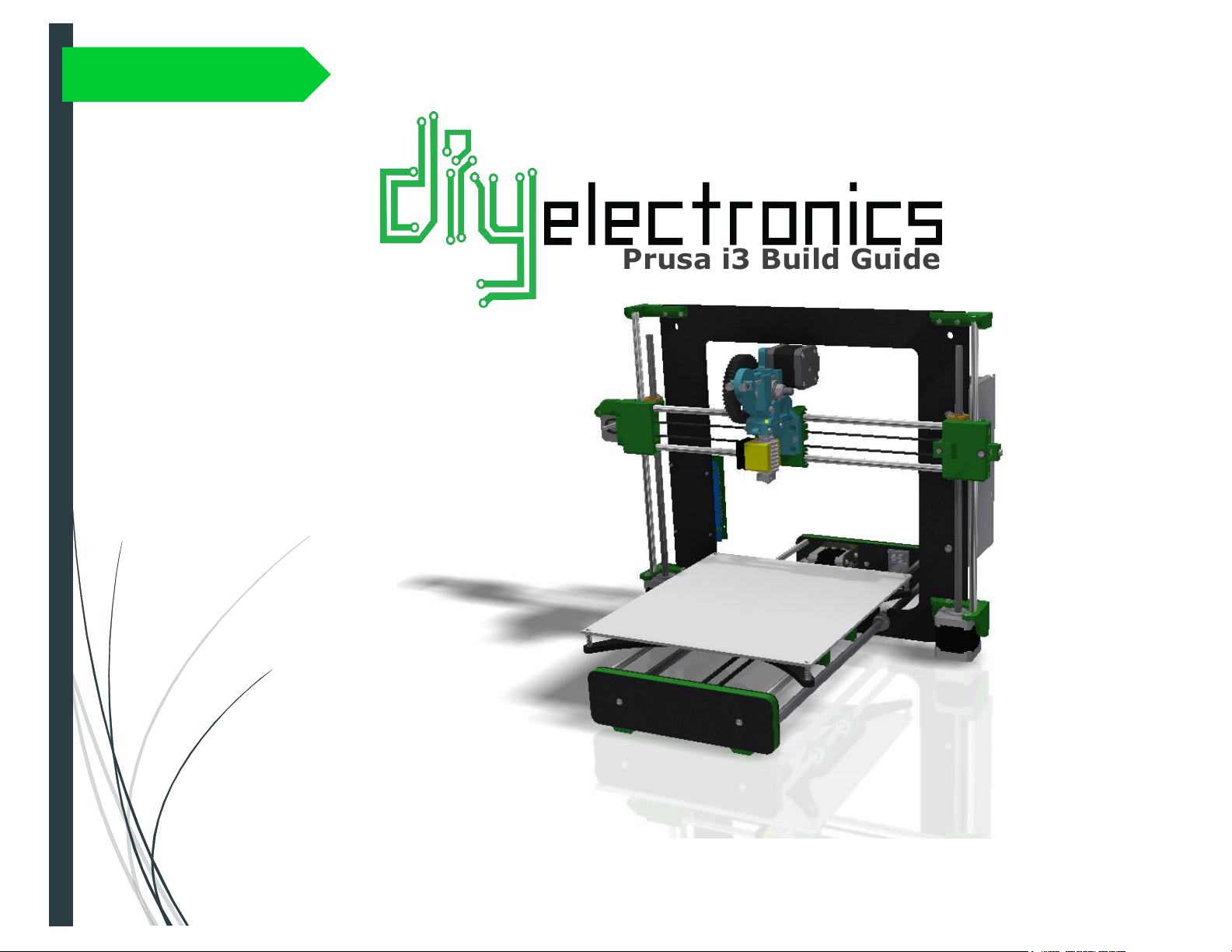
[1.1] Y Carriage –Sub-assembly:
Parts needed:
•1x aluminium carriage
•2x M8x 475mm smooth stainless steel rod
•4x LM8UU linear bearings
•8x printed bearing holders
•1x printed y-belt holder
•2x M3x 10mm ch screws
•8x M3x 25mm ch screws
•10x M3 washers
Slide two LM8UU linear bearings onto each smooth 475 mm rod.
Fix the printed Y-belt to the carriage with the use of two M3x 10
machine screws. Do not worry about the orientation of the Y-
belt, it does not make a difference.
Line the bearings, rods, and printed bearing holders with the
holes in the Y-carriage as shown in the top diagram.
Fasten it all down with eight M3x25 screws (don’t forget the
washers)
TIP* Make sure the linear rods slide smoothly within the
bearings. Overtightening the bearing holders will restrict
movement.

6
[1.2] Y-Bed Undercarriage Sub-assembly
Parts needed:
•2x M10x480 threaded rod
•8x M10 nuts
•8x M10 washers
Thread M10 nuts and washers onto the
two M10 threaded rods as seen in the
image above.
Make sure that the distance between the
outer washer on one side and the
nearest inner washer is 155 mm. This is
important for frame alignment.
7
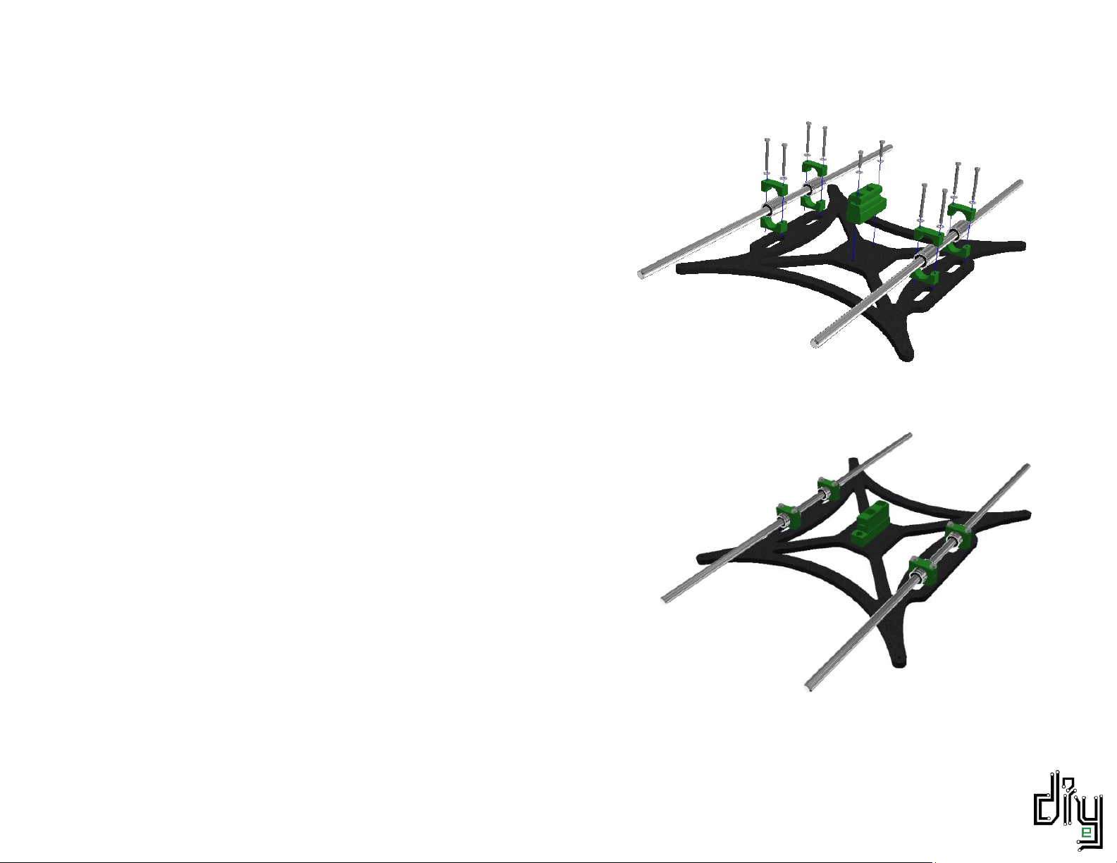
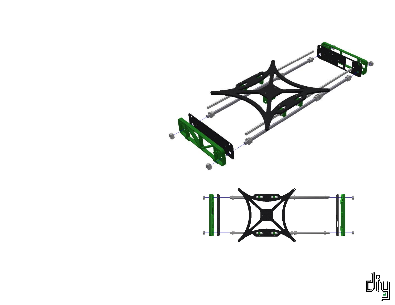
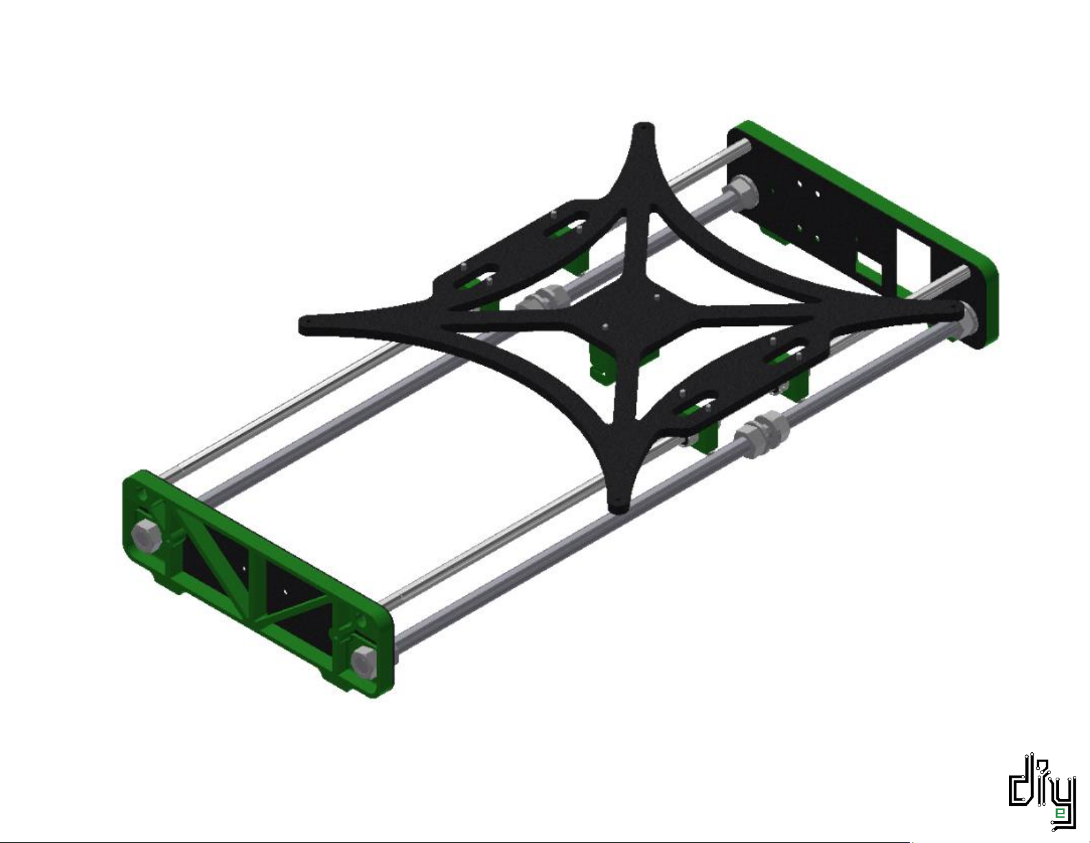
[1.3] Y-Axis assembly
Parts needed:
•Y Carriage Sub-assembly
•Y Bed Undercarriage Sub-assembly
•Inner front plate
•Inner back plate
•Front printed gasket
•Back printed gasket
•4x M10 nuts
Assemble the Y-Axis by sliding the plates
and gaskets onto the ends of the smooth
and threaded rods. The M8 smooth rods
should fit snugly into the printed gasket holes.
There should be exactly enough threaded rod protruding
from the printed gaskets to fit M10 nuts onto.
Tighten these four M10 nuts with a size 17 spanner.
NOTE: Make sure that you tighten the 4 M10 nuts on a
flat surface to ensure a flat Y-Axis assembly.
8

9
[1.4] Y-Belt Idler Pulley Sub-assembly
Parts needed:
•1x printed Y-belt idler (Bearing holder)
•2x 624 flanged bearings
•1x M4x 25 machine screw
•2x M4 washers
•1x M4 nyloc nut
•2x M3x 20 machine screws
•2x M3 washers
•2x M3 nuts
First fasten the printed Y-Belt idler bracket to the front
inner end plate. Use M3x20 machine screws and fasten into
M3 nuts which are to be held captive in the printed bracket.
Feed an M4x25 screw though the bracket and TWO 624
flanged bearings butted up against each other. Don’t forget
about the washers on either side.
Tighten with an M4 nyloc nut. Do not overtighten to allow
your bearing to rotate smoothly.
Altri manuali per PRUSA I3
2
Indice
Altri manuali DIYElectronics Stampante 3D


