DMC Combine CALC-U-DRI II Manuale utente

OWNER’S MANUAL
COMBINE
CALC-U-DRI II
With Averaging
PNEG-1138
PNEG-1138
Date: 9-21-06
TABLE OF CONTENTS
Safety Instructions i
Introduction to DMC’s Combine Calc-U-Dri II 1
Operation 1 - 2
Installation of Control Box & Digital Display 3 - 5
Installation of Sensor 5 - 7
Installation of Averaging Switch 8 - 9
Sampling Procedure 10
Parts Listing 11
Trouble Shooting Guide 12 - 14
Warranty 15
DMC Distribution Centers Listing 15
Offset Recommendations 15
Optional Elevator Sampler Installation 16 - 20
!!CAUTION!!
BE A SAFE OPERATOR
1. Read and understand this Owner’s Manual
2. Stop the combine threshing unit and engine
before sampling, adjusting or servicing.
Use caution when obtaining a sample from
the grain hopper. Follow combine manufac-
turer’s recommendations when climbing in
and out of the hopper.
3. Disconnect all electrical power before
servicing or opening control box.
4. Ground all electrical equipment properly.
5. Only knowledgeable and trained personnel
should operate this equipment.
Failure to follow these instructions may result
in personal injury or property damage.
i
○○○○○○○○○○○○○○○○○○○○○○○○○○○○○○○○○○○○○○○○○○○○○○○○○○○○○○○○○○○○○
OPERATION
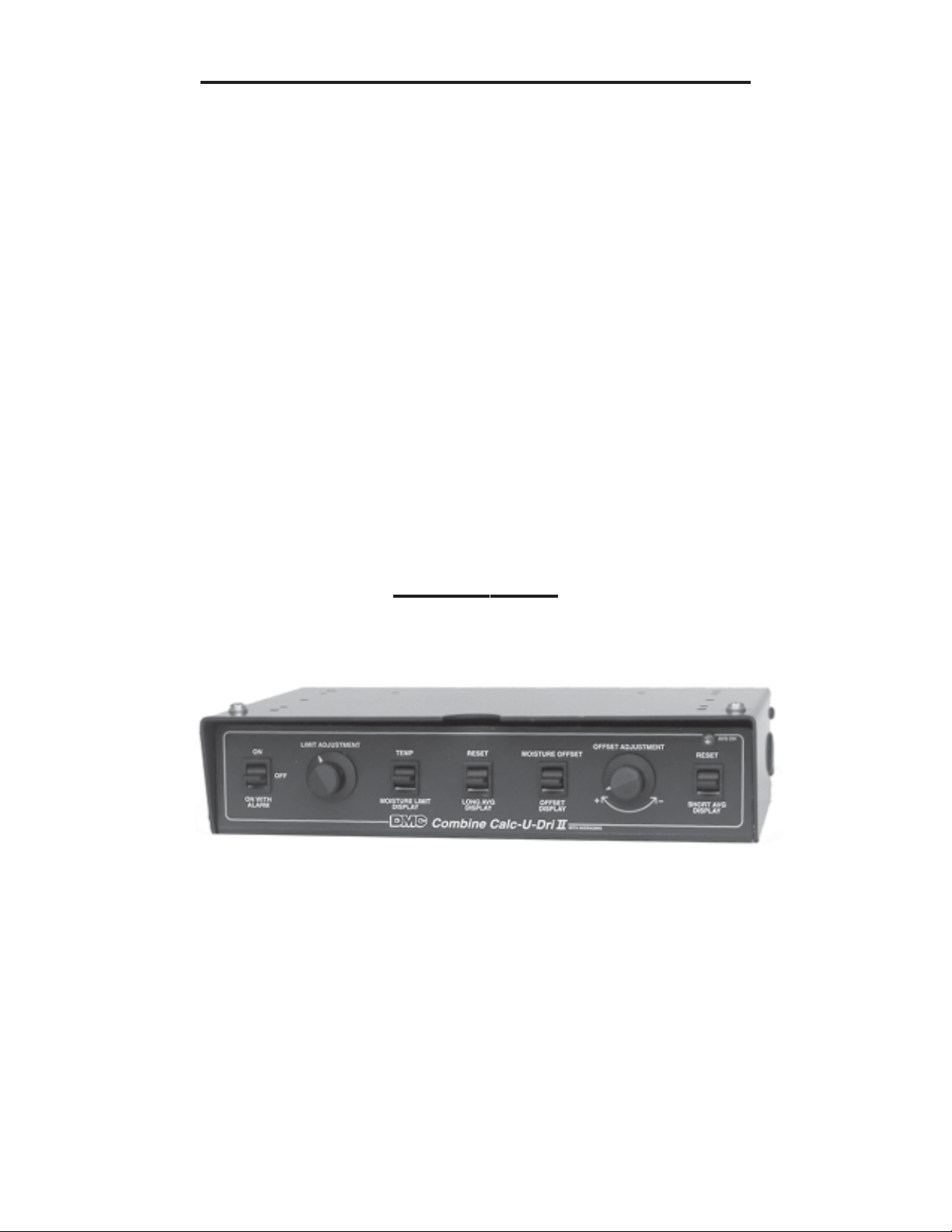
1. The Combine Calc-U-Dri II control box is designed to be mounted to the ceiling of a
combine cab. Always refer to the owners manual for installation and operating infor-
mation. See Photo A.
Photo A
2. Turn the combine ignition switch to the “on” or “accessory” position. Switch the Combine
Calc-U-Dri II power switch “ON”. The digital display should read approximately 2.0% if
the offset is set at zero and there is no grain on the sensor and ambient temperature is at
80 degrees F. Or, it will read the moisture content of any grain that is left on the sensor.
3. Push the “temperature” switch up during harvesting and the digital display will show the
temperature of the grain on the sensor. Normally this will be close to the ambient
temperature.
4. Push the “Moisture Limit Display” switch down and the digital display will read the moisture
limit. Turn the “Limit Adjustment” knob clockwise to increase or counter-clockwise to
decrease the moisture limit.
1
COMBINE CALC-U-DRI II INTRODUCTION
Congratulations on the purchase of your new Combine Calc-U-Dri II from DMC. The
Calc-U-Dri utilizes DMC’s years of experience with grain moisture monitors and controls
in the grain drying industry. Your new Combine Calc-U-Dri was designed by DMC’s
engineers who also farm and utilize this equipment in their farming operations. Since the
Combine Calc-U-Dri was designed by farmers for farmers, you can rest assured that it was
designed specifically for your needs.
The DMC Combine Calc-U-Dri II will monitor grain moisture as it enters the combine hopper
and provide the operator with long and short averages of the grain moisture. A short average
could be just a hopper full of grain. A long average could be an entire truck load or even a
whole field of grain. It will also signal when the moisture content is at or higher than a preset
level as set by the operator. The digital display can be mounted in any location desired. Many
operators mount the display on the steering column for convenience. The display will constantly
show grain moisture content. It will also show grain temperature on demand.
The Combine Calc-U-Dri can easily be calibrated for use on various models of combines and
for different grains by using the moisture offset feature. If you ever have any questions on the
function, design or operation of DMC’s Combine Calc-U-Dri, contact your nearest DMC Sales
and Distribution Center or DMC’s factory in Mason City, Iowa (See the listings on page 15.)

7. The Combine Calc-U-Dri unit needs to be calibrated for different grains and auger
configurations. This is done by comparing the reading on the digital display with the
moisture content reading from a reliable moisture tester.
Note: It is important to take samples when the readings are steady and not changing rapidly
and to use the average of several samples when calibrating the unit to insure accuracy. See
sampling procedure on page 10.
8. Adjust the offset to account for the difference between those readings. Adjust the offset to a
minus value if the Calc-U-Dri readings were higher than the moisture tester’s readings. If the
Calc-U-Dri moisture readings were lower than the moisture tester’s readings, adjust the
offset to a plus value equal to the difference.
9. The Combine Calc-U-Dri II computes two different moisture averages. The short average
can be used for a hopper of grain or just one round in the field. The long average can show
the moisture in a truck load or for one or more fields. To read an average, push either the
“SHORT” or “LONG AVERAGE DISPLAY” switch down.
To reset an average, push the respective switch up and hold until you hear four (4) beeps.
At the end of the fourth beep, the old average will be cleared. A new average will auto-
matically begin if the “AVG ON” indicator is on.
10. The averaging switch, located in the path of the clean grain, signals the Combine
Calc-U-Dri II when switch is covered with grain and valid data is present to be used for
averaging. After a delay of approximately six (6) seconds, the “AVG ON” light will turn
on. This light indicates that the Combine Calc-U-Dri II moisture reading is being used to
update both the short and long averages. If sufficient grain is not present to keep the
average switch covered, the “AVG ON” light will turn off after approximately two (2)
seconds. The two averages will remain in memory for up to three weeks without power
to the Combine Calc-U-Dri II.
2
OPERATION (continued)
5. Switch the power switch to “ON WITH ALARM”. An audible alarm will sound and the red indicator
will light when the moisture content of the grain reaches the moisture limit setting. The alarm will
last about one-half second and will sound each time the moisture limit is reached. If the power
switch is in the “ON” position, the audible alarm will not sound and only the light on the digital
display will come on to alert the operator when the moisture limit is reached.
6. Push the “MOISTURE OFFSET DISPLAY” switch down to read the setting for the mois-
ture offset. It should be set to 0.0% initially before calibration. This can be adjusted to a
plus value or a negative value by turning the “OFFSET ADJUSTMENT” knob.

CONTROL BOX INSTALLATION
1. The Combine Calc-U-Dri II control box is designed to be mounted to the ceiling
of the combine cab or any convenient location. Select a location in the cab and
check the area above for any hoses, tubes or electrical wiring that could be dam-
aged by the control box mounting screws.
2. Open the Calc-U-Dri box by loosening the screws on the front bottom corners.
See Photo B.
3. Hold the box up to the chosen location and
mark the mounting holes through the top of
the box. See Photo B & Diagram 1. (Note:
Six mounting holes are provided in the
Combine Calc-U-Dri box. Use two or four of
the holes to mount the Calc-U-Dri to the
combine ceiling, depending on the
obstructions in the ceiling and/or the
sturdiness of the material from which the
ceiling is made.
Diagram 1
Pilot holes (9/64” diameter) can be drilled or
the self tapping screws that are provided can
be used to secure the box to the ceiling. Double check to make sure that no
components can be damaged in the cab roof area by the mounting screws.
3
Photo B

4. For installations where the control box is to be mounted to a flexible surface, it may
be desireable to use a back-up plate or brackets to stiffen the mounting surface.
Use the cover of the control box as a template to mark the location of the six (6)
mounting holes on the back-up plate or brackets. Drill 0.140 diameter (9/64”) holes
in the back-up plate as pilot holes for the self-tapping screws that are provided for
mounting the box.
When the control box is mounted to a surface or panel that is held in place with
spring clips or other quick-latch devices, make sure that the control box will not
cause the panel to fall. It may be necessary to use additional mounting screws
for the panel or to attach a safety chain to insure that if the panel does become
loose it will not obstruct operation of the combine.
5. Select a location for the digital display such as the back side of the steering column.
Clean off the mounting surface with wood alcohol to remove any oil or dust before
sticking the display to the surface. See Diagram 2.
Diagram 2
6. Use the stick-on clips to route the cable from the digital display to the Calc-U-Dri II
control box.
7. Feed the cable through the grommet on either side of the box and, leaving about
10 inches for connections. Cut off any excess cable.
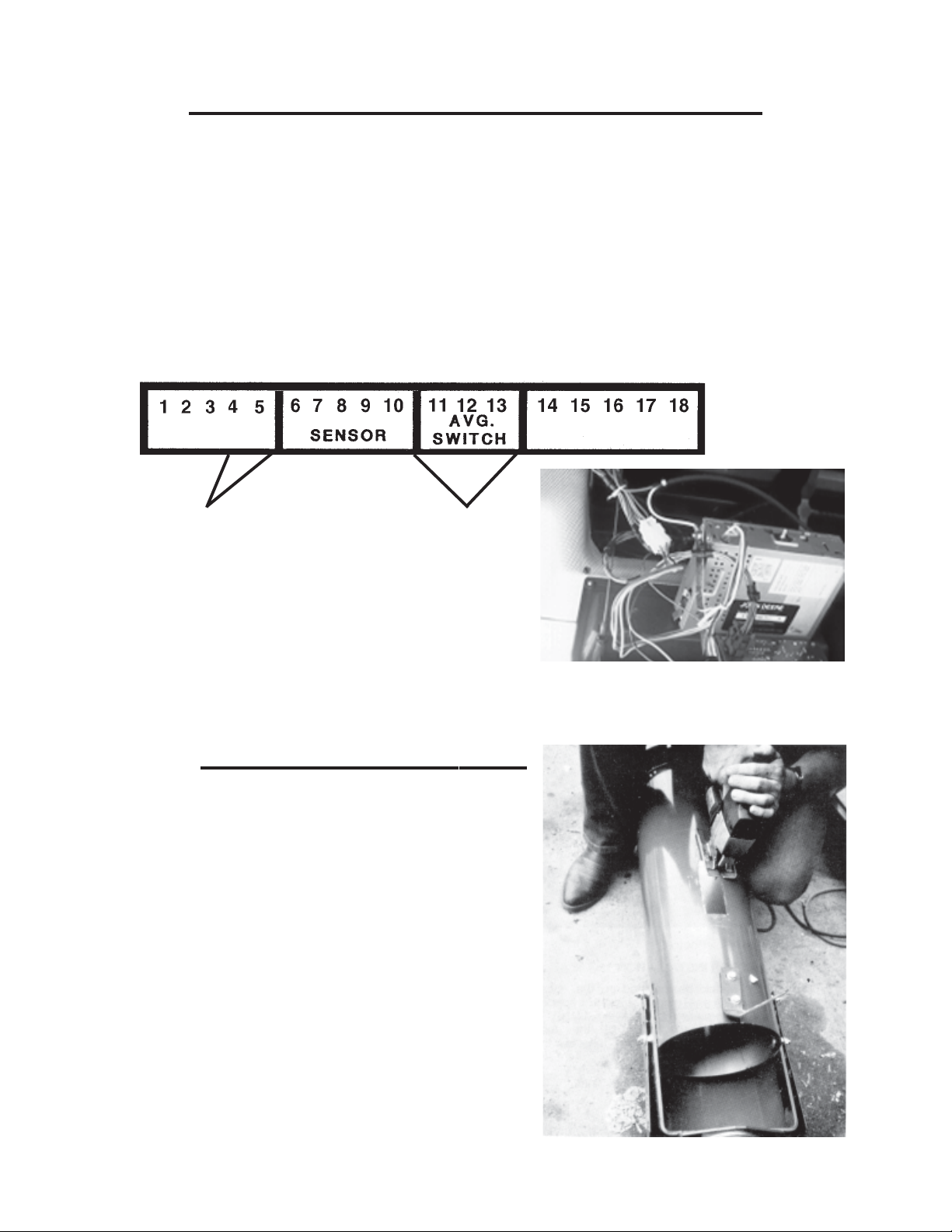
8. Separate the individual wires in the cable. Remove one-quarter inch of insulation
on each wire and connect them to the terminal block posts as marked by the decal
(i.e., white to 18, green to 17, black to 16, brown to 15 and red to 14).
4
CONTROL BOX INSTALLATION (continued)
9. Feed the power supply wires through the same grommet and route them to a
convenient power source in the cab.
Make sure that one end of the red wire is connected to the positive (+) side of a
power source and the other end to terminal number five. Likewise, one end of the
white wire should be connected to the ground (-) side of a power source and the
other end to terminal number four.
Pick up power from a source that is controlled by the ignition switch such as the
radio circuit. Use stick-on clips to route the power supply wires. See Photo C.
CONTROL BOX INSTALLATION (continued)
Photo C
SENSOR INSTALLATION
1. The sensor should be mounted in the
clean grain auger tube in the combine
grain hopper. Use the template provided
to mark a 5-1/16” x 1-11/16” rectangle
on the bottom of the tube about 12 inches
from the end of the tube to the center of
the hole. The template may then be
discarded. Cut this rectangle out carefully
to make sure that the sensor block fits tight.
Do not torch cut! See Photo D.
Photo D
5
12V DC Power Black wire to Terminal 11
Red wire to Termial 5 Yellow wire to Terminal 12
White wire to Terminal 4 Red wire to Terminal 13
(For optional Combine Elevator Side Mount
See Pages 16-20)

SENSOR INSTALLATION (continued)
2. Mark the flighting that sweeps over the sensor hole and disassemble the auger tube
from the flighting.
3. Locate the marks made on the flighting above the sensor hole and weld the flighting
to the auger shaft starting 3/8” beyond each end of the marks.
4. Cut approximately six and one-half inches (6-1/2”) of flighting out between the
welds and smooth out any rough edges on the flighting ends and on the auger
shaft. See Photo E. Notice that the flighting is removed all the way to the shaft.
Photo E
OPTIONAL: The flighting cut out may be used to double the flighting
thickness on each side of the sensor opening. This is optional and
not required.
5. Reassemble the auger tube and check to make sure that the flighting will not
hit the sensor blade, inserting the sensor gauge into the sensor hole and
rotating the flighting. The flighting should clear the gauge. If not, cut out
`` additional flighting.
6. Insert the sensor into the tube and
secure in place with the hose clamp
provided. See Photo F.
(Only one hose clamp is now used.)
Photo F
(New sensors have one clamp)
6

SENSOR INSTALLATION (continued)
7. Use a self drilling screw to attach the ground strap to the auger tube 90 degrees up
from the sensor. See Photo F.
8. Make sure that the sensor is oriented properly in the tube. Note the direction of the
grain flowing over the sensor blade.
9. Route the sensor cable out of the hopper and to the cab. Use hose clamps to
secure the cable to the auger tube if necessary. Use stick-on clips and ties to
route the sensor wire from the hopper to the cab. See Photo G. A clip-on
grommet is provided to seal the cab if a hole must be drilled for entry into the cab.
Use a 15/32 inch diameter drill bit for drilling the hole for the grommet.
Photo G
(New sensors have one clamp)
NOTE: It is important when routing cable that it is attached securely against
something so that the grain being drawn out of the hopper does not pull on the
cable, causing loose or broken connections. See Photo G.
10. Route sensor cable about ten inches
through the grommet in the Calc-U-Dri
box and cut off excess cable. See
Photo H.
11. Remove about three inches of cable
housing and shield and connect the
individual wires to the terminal block
posts according to the decal. (i.e.,
black to six, white to seven, blue to
eight, red to nine and green to ten.)
See Photo H. Photo H
NOTE: The cable shield should not be attached in the control box. Prevent
shield from shorting out by taping any exposed shield.
7
AVERAGING SWITCH INSTALLATION
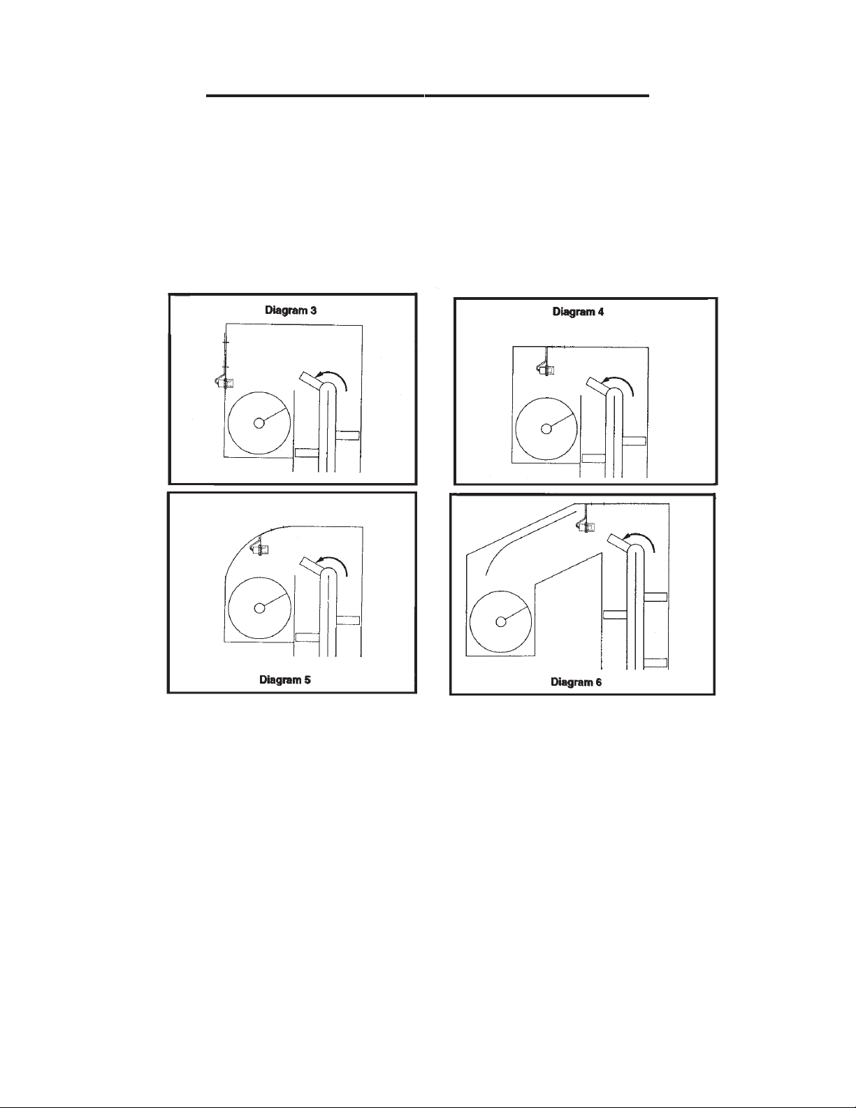
1. The averaging switch should be mounted in the boot housing of the clean grain
auger. so that grain being thrown hits and accumulates on the yellow face of the
switch. See Diagrams 3 - 6. The switch must be horizontal and facing oncoming
grain. Allow clearance for both the auger and elevator, making sure that there will
be nothing on the sensor when the elevator empties. The point at which grain hits
the boot housing can be determined on used combines by finding where the paint
is worn.
2. Position the bracket to locate the mounting holes. See Diagram 3. Drill a 3/8”
diameter hole and a 1-1/8” diameter hole 2-3/4” apart. Attach bracket to the boot
housing with 5/16” x 3/4” bolt, lock washer and nut. If bracket is too long to fit in
housing, cut off excess length. Put switch through the larger hole and fasten with
two nuts supplied. Thread the averaging cup over the switch as shown in
Diagram 7.
3. When mounting the bracket to the top of the boot housing, it must be bent so that
the switch is horizontal. See Diagrams 4 - 6. Position the bracket to locate the
mounting holes and drill two 3/8” diameter holes two inches apart. Attach the
bracket to the top of the boot housing using two 5/16” x 3/4” bolts, lock washers
and nuts. Put the switch through the larger hole and fasten with the two nuts and
average cup supplied. See Diagram 7.
8
Indice
Manuali Unità di controllo popolari di altre marche

Festo
Festo Compact Performance CP-FB6-E Manuale elenco delle parti

Elo TouchSystems
Elo TouchSystems DMS-SA19P-EXTME Manuale utente

JS Automation
JS Automation MPC3034A Manuale utente

JAUDT
JAUDT SW GII 6406 Series Guida rapida

Spektrum
Spektrum Air Module System Manuale utente

BOC Edwards
BOC Edwards Q Series Manuale utente


