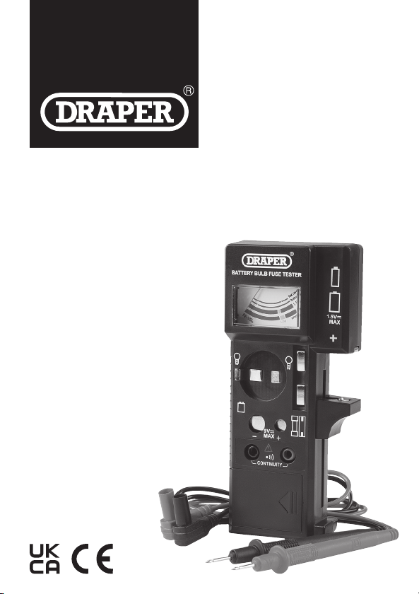
4. Identication
(1) 1.5V battery test contacts
(2) 9V battery test contacts
(3) Fuse storage
(4) Battery compartment
(5) Continuity test probes
(6) Fuse test contacts
(7) Gauge
(8) Lightbulb test contacts
(9) Negative (black) probe
(10) Negative probe terminal
(11) Positive (red) probe
(12) Positive probe terminal
5. OperatingInstructions
Important: Before operating this product, read and understand all the safety
instructions listed in this manual.
5.1 InstallingtheBattery
Slide the battery cover away from the battery compartment (4) on the rear of
the device and connect a 9V PP3 or equivalent battery to the contacts according
to the correct polarity. Insert the battery into the compartment and reinstall
the cover.
Important: DO NOT operate this device without the battery compartment cover
in place.
5.2 Testing1.5VBatteries(AAA,AA,C,Detc.)
1. Position the lower 1.5V battery test contact (1)
as appropriate and insert the battery according
to the marked polarity (Fig. 1).
2. To read the battery level, observe the position of
the gauge (7) needle against the scale band
marked “1.5V”.
− Green: The battery level is good.
− Yellow: The battery level is low.
− Red: The battery level is very low and the
battery cannot be used.
5.3 Testing9VBatteries(6F22,006P,etc.)
1. Connect the battery to the 9V battery test
contacts (2) according to the marked polarity
(Fig. 2).
2. To read the battery level, observe the position of
the gauge (7) needle against the scale band
marked “9V”.
− Green: The battery level is good.
− Yellow: The battery level is low.
− Red: The battery level is very low and the
battery cannot be used.
5.4 TestingFuses
1. Place the fuse against the fuse test contacts (6)
(Fig. 3).
2. To read the state of the fuse, observe the
position of the gauge (7) needle against the
scale band marked “Test continuity”.
− Green: The fuse may be used in an
appropriate appliance.
− Red: The fuse is in an open circuit state.
5.5 TestingBulbs
1. Place the two bulb terminals against two of the
three lightbulb test contacts (8), depending on
the type of bulb (Fig. 4).
2. To read the state of the bulb, observe the
position of the gauge (7) needle against the
scale band marked “Test continuity”.
− Green: The bulb may be used in an
appropriate appliance.
− Red: The bulb is damaged and cannot
be used.
5.6 ContinuityTesting
1. Insert the probe connectors into the
terminals on the device:
− The negative (black) probe (9)
connects to the left (negative)
terminal (10).
− The positive (red) probe (11)
connects to the right (positive)
terminal (12).
2. Disconnect all power to the
circuit to be tested and discharge
all capacitors.
WARNING! NEVER measure
resistance across a voltage
source or on a powered circuit.
3. Connect the probes across the circuit to be tested, observing the
correct polarity.
4. An audible alarm will sound if the circuit resistance is <5,000Ω.
Important: If the resistance is between 5,000–10,000Ω, the alarm may or may
not sound.
6. ProductCare,StorageandDisposal
• Keep the product clean and free from dust, debris and grease.
• Use a dry cloth ONLY to clean the housing of this device.
CAUTION! DO NOT use abrasives, solvents or other aggressive
chemicals as these may damage plastic or insulated parts.
• Replace the probes IMMEDIATELY if they are damaged in any way or the
conductors are exposed; contact Draper Tools for replacement options.
• Remove the battery when storing the device for extended periods; it can be
stored in the battery storage compartment (4).
• Store the device in a cool, clean and dry environment, out of direct sunlight
and out of reach of children.
At the end of its working life, dispose of the product responsibly and in line with
local regulations. Recycle where possible.
• DO NOT dispose of this product with domestic waste; most local authorities
provide appropriate recycling facilities. [add WEEE symbol]
• DO NOT burn or mutilate batteries; this may release toxic or corrosive
substances. [add re symbol]
• Dispose of batteries separately and in accordance with local regulations.
7. Warranty
Should the tool develop a fault, return the complete tool to your nearest
distributor or contact Draper Tools directly. Proof of purchase must be provided.
If, upon inspection, it is found that the fault occurring is due to defective
materials or workmanship, repairs will be carried out free of charge. This warranty
covers parts and labour for 12 months from the date of purchase. However, if the
tools are hired out, the warranty period is 90 days from the date of purchase.
This warranty does not apply to any consumable parts, batteries or normal wear
and tear, nor does it cover any damage caused by misuse, careless or unsafe
handling, alterations, accidents, or repairs attempted or made by any personnel
other than the authorised Draper Tools repair agent.
Visit drapertools.com/warranty for full details.
Fig. 1
Fig. 2
Fig. 3
Fig. 4
Fig. 5
(6)
(1)
(12)
(1)
(4)
(2)
(10)
(3)
(5)
(8)
(7)
(11)
(9)