E-Plex 413DWM Manuale utente

Powering systems - Empowering designers
413DWM
Design Specifications
• Shock: Mil Std 202 Method 213 test condition 1.
• Vibration: Tested to Lloyds Register Approval Vibration
Test 2.
• Transient voltage suppression: EN6100-6-1.
• Moisture resistance: IP66.
• PCB characteristics: UL94V-0.
• Power distribution: UL 1077 compliant (except high-
voltage dielectric test).
• Ignition protection: UL 1500 compliant.
• Salt spray: Tested to Lloyds Register Approval Salt Spray
Test.
• Operating Temperature: -40°C to 60°C.
• Storage Temperature: -40°C to 85°C.
• Operating Humidity: 0% to 100% (condensing).
• Weight: 1.34 lb (610g).
Key Features
• 6 channels with outputs capable to 15 amps each (50
amps total).
• 4 channels are diode protected against back feeding.
• 2 channels with PWM dimming capabilities.
• Reverse battery protected.
• Status LED’s for each channel.
• Thermal, short circuit, and programmable overload
protection.
• Local electronic override capabilities.
• Designed for motor loads.
• LEN value 2.
Introduction
The E-Plex®413DWM is a six channel DC power distribution module capable of handling loads of up to 15A
per channel or 50A total. The six channels can be utilized as either inputs, outputs, or a combination of both.
The individual channels may be combined in order to handle larger amperage loads.
With four diode protected channels the module and E-Plex system are protected from being back-fed. This
protection is required in applications where the module is wired in parallel with a system that may be powered
by an additional external source. An example of this includes a bilge pump controlled by a float switch along
with an E-Plex module.
Local electronic override capabilities allow independent operation of the device loads. In addition, the
413DWM design allows for the ability to utilize up to two channels as dimmer circuits, providing a flexible
solution for lighting without requiring additional external dimming hardware.
Hexa Multi Module,
Diode Protected
Powering systems - Empowering designers
413DWM
Electrical Specifications
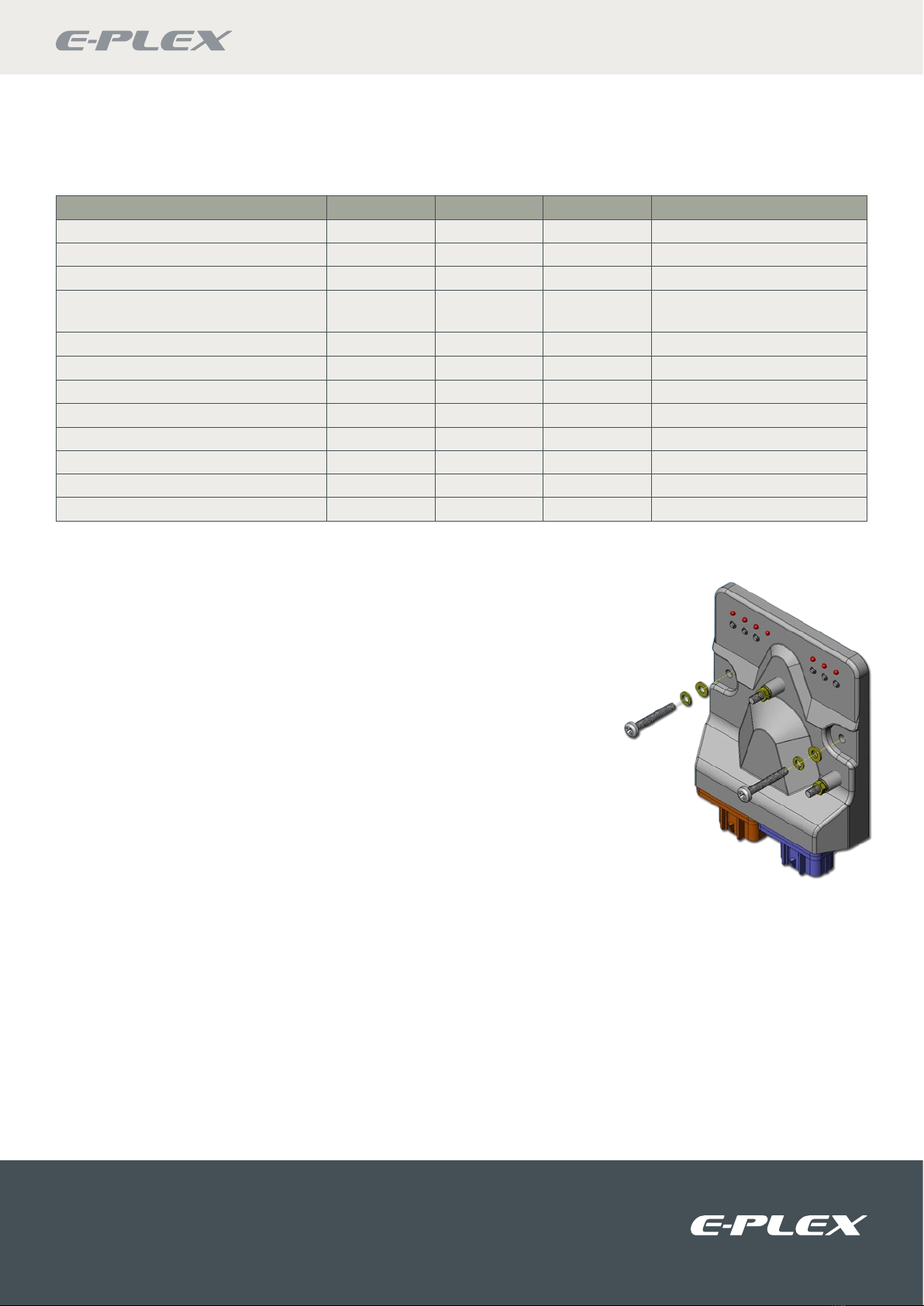
Mounting Instructions
Screw assembly to a flat mounting surface in 2 places, as shown in the
illustration.
Imperial (English) fasteners: Use #10 size screw, #10 split lock washer, #10
washer. Torque to 20~22 in-lb. Do not exceed this torque as it could cause
damage to the electronics.
Metric fasteners: Use M5 size screw, M5 split lock washer and M5 washer.
Torque to 250~280 N-cm. Do not exceed this torque as it could cause
damage to the electronics.
NOTES:
1. De-rate max current by 0.2 A per °C above ambient, 25°C.
2. Measured at 8.3 ms single half sine wave. (JEDEC Method).
3. Duty cycle at 1 minute on time, 5 minutes off. Trip delay must
be set to maximum rating.
4. Single pulse only.
5. Measured at 10 A load.
6. PWM not recommended for motor loads unless factory
authorized.
7. For load resistance greater than 2 ohms load inductance is
unlimited.
8. Specified as 50 feet of 2 AWG (43 mm²) wires with a 6 inch
diameter spool for both power and ground.
9. For a channel configured as an input this specifies the turn-on/
off threshold impedance @ 50K.
Description Minimum Nominal Maximum Absolute Maximum (Surge)
Voltage 7 VDC 12/24 VDC 32 VDC 45 VDC
Current, Total 0.025 A 30 A 50 A 1160 A 2
Current, per channel continuous 0 12 A 15 A 80 A 4
Current, per channel
intermittent duty 30 – 20 A 80 A 4
Inrush capable per channel – – 80 A 80 A 4
Input low threshold 90 V – 3.5 V –
Input high threshold 94.5 V – 32 V –
Lead inductance 0 – 100 µH 8–
Load Inductance 70 – 20 mH –
PWM Frequency 60 Hz 122 Hz – -
Output Impedance 510 mΩ 12 mΩ 14 mΩ
Diode Protection (Back-Feed) 0 - 20A -
The supply to the module should be protected by a fuse or circuit breaker, 50A maximum
Powering systems - Empowering designers
413DWM
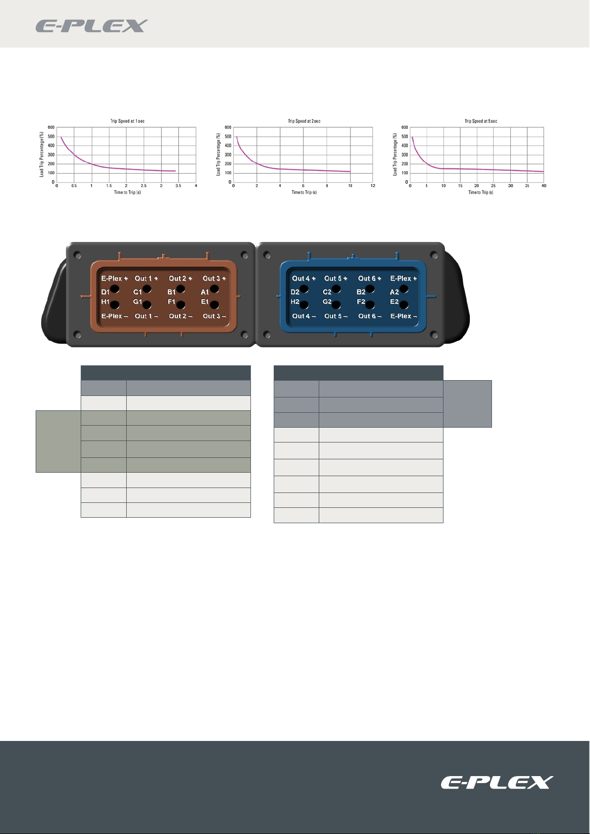
Trip Speed Characteristics
Wiring Specifications
Pin # Pin Description
A1 Solid State Output 3
E1 Output 3 Return
PWM
Capable
B1 Solid State Output 2
F1 Output 2 Return
C1 Solid State Output 1
G1 Output 1 Return
D1 E-Plex Data Bus +
H1 E-Plex Data Bus –
M5-T1 Battery Power
Pin # Pin Description
D2 Solid State Output 4
Diode
Protected
C2 Solid State Output 5
B2 Solid State Output 6
A2 E-Plex Data Bus +
E2 E-Plex Data Bus -
F2 Output 6 Return
G2 Output 5 Return
H2 Output 4 Return
M5-T2 Battery Return
Outputs and Returns: 0 to 15A, 7-32VDC
The first two outputs (C1, B1) are PWM capable and may be used to dim lighting loads. Channels A1 and B2 through D2
incorporate a diode to protect against back-feeding from an external source.
Battery Power (+): 0.025A to 50A, 7-32VDC
Status LEDs:
ON - Channels 1-6 indicates Load ON, E-Plex channel indicates module responding.
OFF - Channels 1-6 indicates Load OFF, E-Plex channel indicates module not responding. 10
BLINKING - Channels 1-6 indicates Load FAULT, E-Plex channel indicates module responding.
Power / Battery Connections: Must be fused at a maximum of 50A. Maximum wire size should be sized based on upstream fuse.
When connecting the power source to the power studs on the module, torque the M5 hex nuts should be torqued to 20~22 in
lb or 250~280 n-m after installing the battery terminals to the studs. Failure to properly torque hex nuts may result in intermittent
operation due to terminals loosening over time. Note: External surge suppression is required when the module battery supply
cable is longer then 50’ (25’ for any 2 outputs that are paralleled).
Reversed Battery Conditions: The loads will turn on, but no damage will occur to the module if disconnected within 1 minute
(Under nominal operating load conditions).

Powering systems - Empowering designers
413DWM
Pin Specifications
Typical Wiring Diagram
NOTES:
10. LED will be off if system is not functioning or present, however, modules in the system may still be responding.
11. Manual override switches are meant to be used as a local electronic manual override for emergency situations only.
12. Load activation function for switches 1 thru 6 are defined in E-Logic as either toggle or momentary operation.
13. Diode is incorporated to protect channel from back-feeding from an external source.
Cable Range AWG (mm2)Female Terminal Terminal Insulation
Range
Seal Insulation
Range Seal P/N
18-16 (1.0-0.75 mm2) 15304716 1.70-2.25 mm 1.20-1.85 mm 15366063
1.85-2.25 mm 15356064
16-12 (2.50-1.50 mm2) 15304717 2.20-3.00 mm 2.09-2.66 mm 15366061
2.70-3.2 mm 15336674
Status LEDs,
Channels 1 - 6
and E-Plex10
Ch. 6
Ch. 5
Ch. 4
Ch. 3
Ch. 2
Ch. 1
E-Plex
Channels 1-6,
Override Switches
11,12
M5 - T2
M5 - T1
+
Battery Return
(Ground)
E-Plex +
E-Plex –
D1
H1 Lamp
C1
B1
A113 Pump
G1
F1
E1
Pump
Motor
E2
A2
H2
G2
F2
D213
C213
B213
E-Plex
+E-Plex
–
Lamp
Motor
12VDC or 24VDC,
Battery power protected by a fuse
or circuit breaker, 50A maximum

Powering systems - Empowering designers
413DWM
Dimensional Diagram
Mechanical Specifications Ordering Information
Description E-Plex Part Number
413DWM Series - Hexa
Multi Module, Diode
Protected
EP-SW-IO-6CH-413DWM
Connectors:
J1 - Brown: Mates to Delphi P/N 15317308
J2 - Blue: Mates to Delphi P/N 15317304
Cavity Plug:
Delphi P/N 12059168
Power Stud Connections:
M5 nickel plated brass
127mm [5.00”]
63.5mm [2.50”]
113.3mm [4.46”]
13.7mm [0.54”]
73.7mm
[2.90”]
92.7mm
[3.65”]
135.6mm
[5.34”]
45.7mm
[1.80”]
Ø0.39 [Ø9.91]
Ø 6.10mm [0.24”] x 2]
Ø 5.08mm
[0.20”]
12.9mm [0.51”]
11.9mm [0.47”]
8.1mm [0.32”]
4.8mm [0.19”]
63.5mm
[1.50”]

52 – 54 Riverside, Sir Thomas Longley Road, Medway City Estate, Rochester, Kent ME2 4DP
tel: +44 (0)1634 711622 fax: +44 (0)1634 290773
email: [email protected]
web: www.e-plex.co
Important Notice: E-Plex Ltd. (E-Plex) reserves the right to make changes to or discontinue any product or service identified in this publication without notice. E-Plex advises its customers to obtain
the latest version of the relevant information to verify, before placing any orders, that the information being relied upon is current. E-Plex assumes no responsibility for infringement of patents or
rights of others based on E-Plex applications assistance or product specifications since E-Plex does not possess full access concerning the use or application of customers’ products. E-Plex also
assumes no responsibility for customers’ product designs.
Powering Systems - Empowering Designers
Indice
Altri manuali E-Plex Unità di controllo

Manuali Unità di controllo popolari di altre marche

Festo
Festo Compact Performance CP-FB6-E Manuale elenco delle parti

Elo TouchSystems
Elo TouchSystems DMS-SA19P-EXTME Manuale utente

JS Automation
JS Automation MPC3034A Manuale utente

JAUDT
JAUDT SW GII 6406 Series Guida rapida

Spektrum
Spektrum Air Module System Manuale utente

BOC Edwards
BOC Edwards Q Series Manuale utente


