AMETEK CTS BS 200N100
Operating manual V 1.12 3 / 21
Contents
1. Standards covered by BS 200N100 .............................................................................................................4
1.1. Maximum applicable dc voltage supply ................................................................................................4
2. Operating functions ......................................................................................................................................5
2.1. Operating elements on the top side......................................................................................................5
2.2. Operating elements Front- and Rearside..............................................................................................6
3. Equipment description .................................................................................................................................7
3.1. Electronic switch ...................................................................................................................................7
3.2. Divider 1:200.........................................................................................................................................7
3.3. Air cooling..............................................................................................................................................7
4. Technical Data ...............................................................................................................................................8
4.1. Technical data BS 200N100 .................................................................................................................8
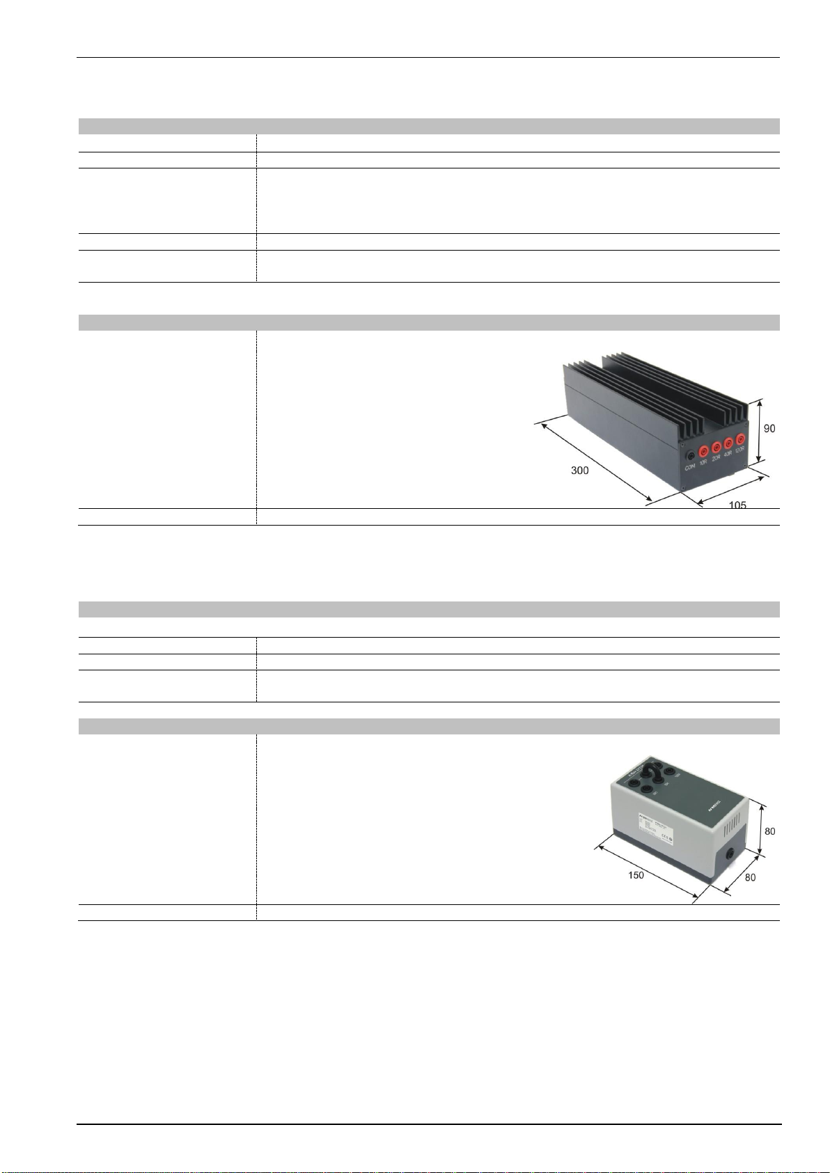
4.2. Technical data CA BS 200N .................................................................................................................9
4.3. Technical data Shunt resistor RS-Box................................................................................................10
4.4. R-Box LV124 Resistor box..................................................................................................................10
5. Calibration / Measuring procedure4..........................................................................................................11
5.1. Test load CABS 200N.........................................................................................................................11
5.2. Test voltage.........................................................................................................................................11
5.3. Switch-Off fall time ..............................................................................................................................11
5.4. Measuring results................................................................................................................................12
5.4.1. Voltage drop in dependence of the test load ......................................................................................12
5.4.2. Measuring results with verification set-up as per Standard ................................................................12
5.4.3. Verification...........................................................................................................................................12
6. Maintenance.................................................................................................................................................13
6.1.General................................................................................................................................................13
6.2. Calibration and Verification.................................................................................................................13
6.2.1. Factory calibration...............................................................................................................................13
6.2.2. Guideline to determine the calibration period of EM Test instrumentation.........................................13
6.2.3. Calibration of Accessories made by passive components only:.........................................................13
6.2.4. Periodically In-house verification.........................................................................................................13
7. Application...................................................................................................................................................14
7.1. Test setup ISO 7637-2 Ed.3 (2011)....................................................................................................14
7.2. LV 124 Test E-10 short interruption Text case 3 ................................................................................16
8. Delivery Groups...........................................................................................................................................17
8.1. Basic equipment..................................................................................................................................17
8.2. Options................................................................................................................................................18
9. Appendix ......................................................................................................................................................19
9.1. Declaration of CE-Conformity .............................................................................................................19
9.2. BS 200N100 - Overview......................................................................................................................20
9.3. CA BS - Overview ...............................................................................................................................21