AMETEK CTS VDS 200Q10 Series
Manual for Operation V 1.00 3 / 35
Contents
1. Model Overview .............................................................................................................................................4
1.1. VDS 200Q10 series models .........................................................................................................................4
1.2. Construction..................................................................................................................................................4
2. Operating Functions .....................................................................................................................................5
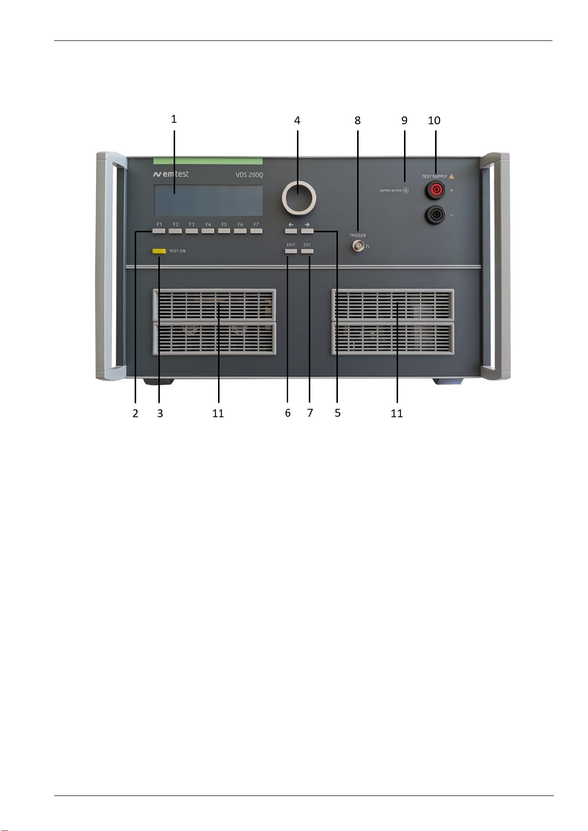
2.1. Front view VDS 200Q10.x ............................................................................................................................5
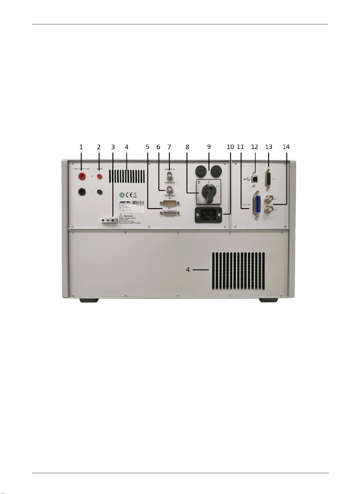
2.2. Rear view VDS 200Q10.x.............................................................................................................................6
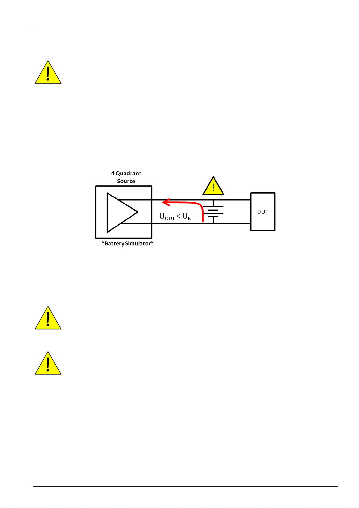
2.3. Safety with voltage setting............................................................................................................................8
3. Operation......................................................................................................................................................10
3.1. Description of the menus............................................................................................................................10
3.2. Main Menu ..................................................................................................................................................10
3.2.1. Change of parameters................................................................................................................................11
3.3. Wave Simulator...........................................................................................................................................12
3.3.1. ISO 7637.....................................................................................................................................................13
3.3.1.1. Pulse 4 voltage drop..................................................................................................................................13
3.3.1.2. Pulse 2b......................................................................................................................................................13
3.3.2. ISO 16750-2 WD 03/2000-2.......................................................................................................................14
3.3.2.1. Short voltage drop.......................................................................................................................................14
3.3.2.2. Slow decrease / increase............................................................................................................................14
3.3.2.3. Supply voltage profile..................................................................................................................................15
3.3.2.4. Pulse ’Starting profile’ .................................................................................................................................15
3.3.2.5. Sinus Sweep...............................................................................................................................................16
3.3.2.6. Overvoltage Vmax ......................................................................................................................................16
3.3.3. Functions ....................................................................................................................................................17
3.3.3.1. Sine wave ...................................................................................................................................................17
3.3.3.2. Jump Start...................................................................................................................................................18
3.3.3.3. VDS Externally via the analog input ...........................................................................................................18
3.3.3.4. Pulse 4 ( GM 9105 P) .................................................................................................................................19
3.3.3.5. DC source...................................................................................................................................................20
3.4. Service........................................................................................................................................................21
3.5. Setup...........................................................................................................................................................22
3.6.Source Settings...........................................................................................................................................23
4. Technical Data.............................................................................................................................................27
4.1. Test level.....................................................................................................................................................27
4.2. Trigger.........................................................................................................................................................27
4.3. Input/output.................................................................................................................................................27
4.4. Interfaces ....................................................................................................................................................27
4.5. General .......................................................................................................................................................28
4.6. Environmental conditions............................................................................................................................28
5. Maintenance.................................................................................................................................................29
5.1. General .......................................................................................................................................................29
5.2. Test set-up..................................................................................................................................................29
5.3. Test set-up with software iso.control ..........................................................................................................29
5.4. Example Test setup with VDS 200Q10.x, AutoWave and PFM 200N100 .................................................30
5.5. Example Test setup with AutoWave and VDS 200Q10.x...........................................................................31
5.6. Calibration and Verification.........................................................................................................................32
5.6.1. Factory calibration.......................................................................................................................................32
5.6.2. Guideline to determine the calibration period of AMETEK CTS instrumentation.......................................32
5.6.3. Calibration of Accessories made by passive components only:.................................................................32
5.6.4. Periodic In-house verification......................................................................................................................32
6. Delivery Groups...........................................................................................................................................33
6.1. Basic equipment VDS 200Q10.x ................................................................................................................33
6.2. Accessories and options.............................................................................................................................33
6.3. Connectors..................................................................................................................................................33
7. Appendix ......................................................................................................................................................34
7.1. Declaration of CE-Conformity.....................................................................................................................34
7.1.1. Declaration of CE-Conformity VDS 200Q10...............................................................................................34
7.1.2. Declaration of CE-Conformity VDS 200Q10.1............................................................................................35