4
010.8030.1222 12.22
Underwriters Laboratories, Inc. (UL) under UL File MH64314.
The EPSC is listed to UL 1738 Venting Systems for Gas-
Burning Appliances, Categories II, III, and IV (480°F Vent
Listing) / ULC S-636 Standard for Type BH Gas Venting
Systems (480°F Venting Listing)
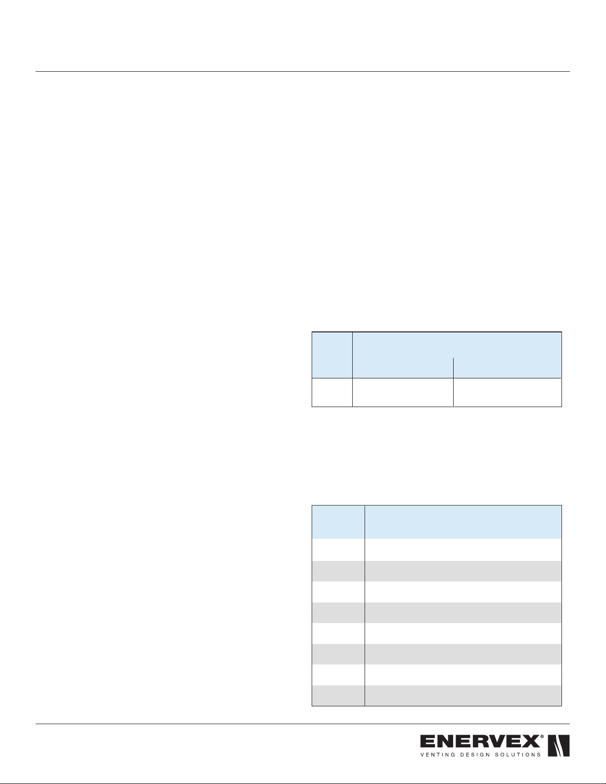
Under this category, EPSC in diameters 4” to 14” has
been determined suitable for venting of ue gases at a
temperature up to 480°F (249°C) from gas red appliances.
See Section 1.10 Clearances” for specic details.
1.5 GENERAL INSTALLATION REQUIREMENTS
When venting Category II, III, or IV appliances or TYPE L
vented appliance, Powerstack must be used for the entire
length of the system. Do not mix pipe, ttings, or joining
methods from different manufacturers
Refer to the gas appliance manufacturer’s instructions to
determine venting requirements and limitations with respect
to installation and use of the appliance. It is the responsibility
of the installer to contact local building and re ofcials
concerning any installation restrictions and/or inspection
requirements that may apply.
Permits may be required before starting an installation.
If required by the appliance manufacturer, a Drain Tee Cap
must be located as close as possible to the appliance ue
outlet. Depending on the arrangement of the vent, more than
one drain may be required.
Only one Category II, III, IV appliance shall be connected
into a venting system, unless the appliance manufacturer
specically approves a multiple venting system. Cat. II, III
or IV appliances SHALL NOT be common vented with Cat.
I, natural draft appliances. This limitation can be ignored
if an engineering analysis demonstrates normal and safe
operation of appliances.
Powerstack shall not be routed into, through, or within any
vent, such as an existing masonry or factory-built chimney,
that is connected to another appliance.
Any horizontally installed portion of the venting system shall
have a slope (upwards for Category II, III, or IV appliances
or downwards for Category III or IV appliances) not less
than 1/4 inch (6.4 mm) every 12 inches (305 mm) to prevent
collection of condensate at any location in the assembly; and
means shall be provided for draining the condensate.
Due to possible ice build up and blockage, it is required
that the proper sloping be employed when the vent is
installed in a horizontal installation. Refer to the appliance
manufacturer’s installation instructions for further details
regarding the installation of the condensate drain ttings;
A venting system that is mounted at the exterior shall be
enclosed below the roof line to limit condensation and
protect against mechanical damage.
After installation, the joints and seams shall be checked
for gas tightness when using the venting system with a
Category III or IV appliance.
1. GENERAL INFORMATION
1.1 INTRODUCTION
These instructions comprise both general guidelines and
special requirements for all parts in the product line. Before
specifying a design or beginning an installation please
carefully review these instructions.
Contact Local Building or Fire Ofcials About Restrictions and
Installation Inspection in Your Area.
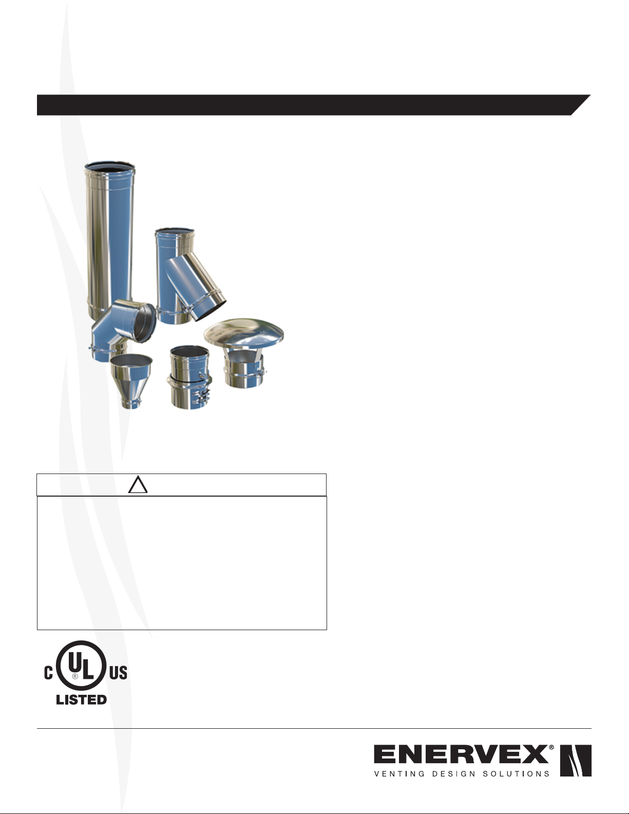
1.2 FEATURES
The PowerStack EPSC are made for residential, commercial
and industrial applications. It is a factory made modular
stainless steel venting system designed for quick assembly.
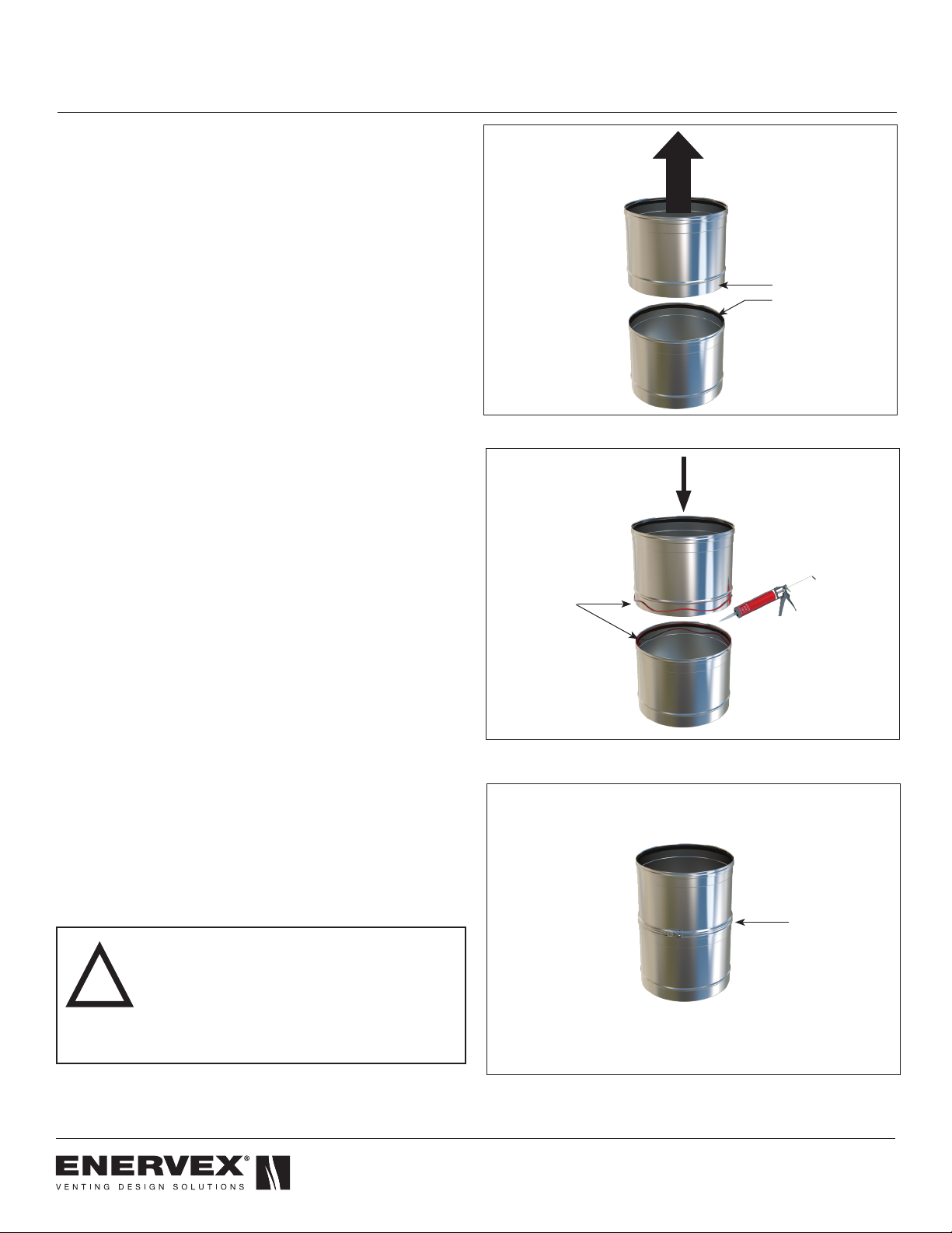
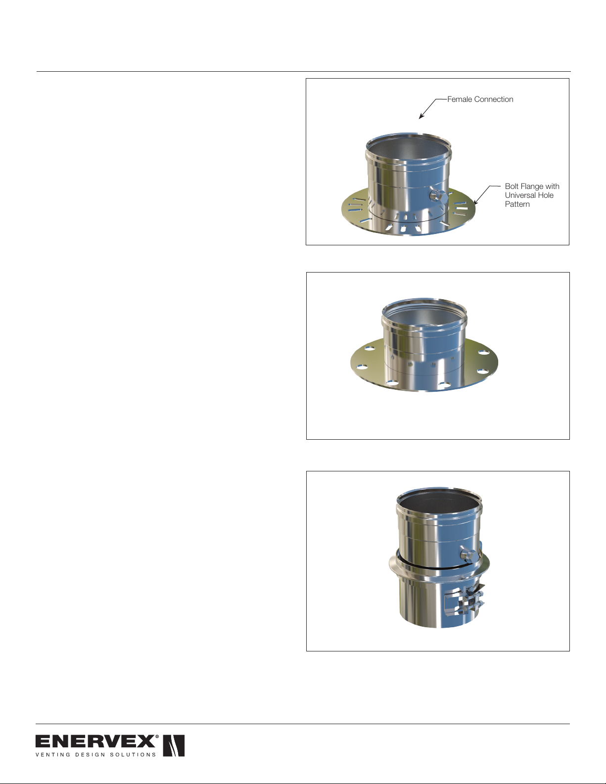
All parts have a male and female end with an Elastomer Triple
Lip Seal.
The PowerStack is offered in a single wall version and is
available in internal diameters ranging from 4” (100mm) to
14” (350mm).The fully welded liner is manufactured from a
special corrosion resistant 316L PCM (Puried Chromium
and Molybdenum).
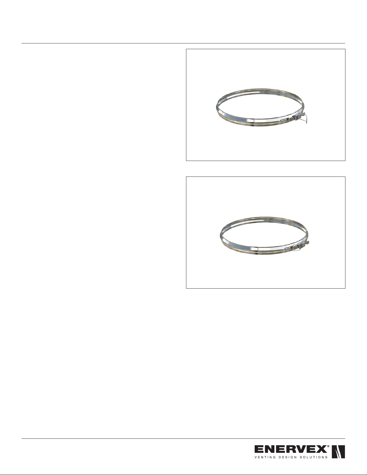
A pressure capability of up to 15”Wg (3,745Pa) and
condensate containment is achieved by using a Elastomer
Triple Lip Seal as part of a simple push-t joint design that is
held in place with a lever type locking band.
All Powerstack models (EPS, EPSA, EPSC, EPS1, EPS2,
EPS3 and EPS4) may be intermixed in the same venting
system, provided the proper associated airspace clearances-
to-combustibles are maintained.
PowerStack EPSC is suitable for negative, neutral or positive
pressure applications and intended for use in a variety of
applications including, but not limited to, Special Gas Vent for
Category II, III and IV.
1.3 SYSTEM DESIGN AND CALCULATIONS
Complete system sizing and capacity information may
be obtained from the “Chimney, Gas Vent, and Fireplace
Systems” chapter of the ASHRAE Handbook, from
the ENERVEX “Chimney and Exhaust System Design
Handbook”, or by contacting ENERVEX Technical Support.
In spite of any sizing guidelines, when sizing venting systems,
it is most important that the appliance manufacturer’s
installation instructions be followed.
Failure to follow these instructions may result in inadequate
vent system performance and/or a violation of the equipment
manufacturer’s installation requirements. Proper operation
of the venting system and appliance is dependent on the
use of all parts specied by the manufacturer for use in the
particular installation. The performance of the system may
be affected if the proper assembly of all required parts is not
accomplished.
1.4 UNDERWRITERS LABORATORIES LISTINGS
The ENERVEX PowerStack EPSC venting system is Listed by