
ESD electronic CAN-USB/2 Manuale di istruzioni
Installation and technical Data CAN-USB/2 Rev. 1.0
esd electronic system design gmbh
Vahrenwalder Str. 207 • 30165 Hannover • Germany
www.esd-electronics.com • Fax: 0511/37 29 8-68
Phone: 0511/37 29 80 • International: +49-5 11-37 29 80
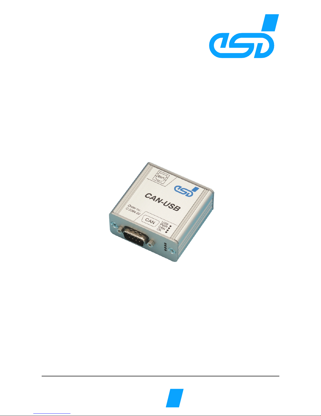
CAN-USB/2
USB 2.0-CAN-Interface
Hardware Installation
and
technical Data
to Product C.2066.xx

Installation and technical Data CAN-USB/2 Rev. 1.0
N O T E
The information in this document has been carefully checked and is believed to be entirely reliable. esd
makes no warranty of any kind with regard to the material in this document, and assumes no
responsibility for any errors that may appear in this document. esd reserves the right to make changes
without notice to this, or any of its products, to improve reliability, performance or design.
esd assumes no responsibility for the use of any circuitry other than circuitry which is part of a product
of esd gmbh.
esd does not convey to the purchaser of the product described herein any license under the patent rights
of esd gmbh nor the rights of others.
esd electronic system design gmbh
Vahrenwalder Str. 207
30165 Hannover
Germany
Phone: +49-511-372 98-0
Fax: +49-511-372 98-68
E-mail: info@esd-electronics.com
Internet: www.esd-electronics.com
USA / Canada:
esd electronics Inc.
525 Bernardston Road
Suite 1
Greenfield, MA 01301
USA
Phone: +1-800-732-8006
Fax: +1-800-732-8093
E-mail: us-sales@esd-electronics.com
Internet: www.esd-electronics.us
Installation and technical Data CAN-USB/2 Rev. 1.0
Document file: I:\texte\Doku\MANUALS\CAN\USB-2\Englisch\USB-2_01.en9
Date of print: 22.06.2006
PCB version: CAN-USB/2 Rev. 1.2
Changes in chapters
The changes in the document listed below affect changes in the hardware as well as changes in the
description of facts only.
Chapter Changes versus previous version
- First issue
Technical details are subject to change without further notice.

Installation and technical Data CAN-USB/2 Rev. 1.0
This page is intentionally left blank.

Installation and technical Data CAN-USB/2 Rev. 1.0 1
Content
1. Overview .................................................................3
1.1ModuleDescription.......................................................3
1.2CaseViewwithLEDandConnectorDescription.................................4
1.3LED-Displays ...........................................................5
2. Hardware Installation .......................................................6
3. Summary of technical Data ................................................... 7
3.1GeneraltechnicalData..................................................... 7
3.2 USB-Interface and Microcontroller ...........................................7
3.3CANInterface...........................................................8
3.4 Software Support ........................................................8
3.5Order Information ....................................................... 9
4. Connector Assignment ..................................................... 10
4.1 CAN Interface at DSUB9 Connector ......................................... 10
4.2USB-Socket ........................................................... 11
5. Correctly Wiring Electrically Isolated CAN Networks ............................ 12
6. CAN-Bus Troubleshooting Guide ............................................. 16
6.1Termination ........................................................... 16
6.2CAN_H/CAN_LVoltage ................................................. 17
6.3Ground ............................................................... 17
6.4CANTransceiverResistanceTest ........................................... 18

Installation and technical Data CAN-USB/2 Rev. 1.0
2
This page is intentionally left blank.
Overview
Installation and technical Data CAN-USB/2 Rev. 1.0 3
+5 V=
+5 V=
Physical
CAN
Layer
C
A
N
B
U
S
CAN
ARM
LPC 2292
CAN
16 kB RAM
256 kB Flash
USB Controller
LEDs
Digital
Isolator
Electrical Isolation
DC/DC
Converter
DSUB9
CiA pinning
Power
Supply
5 V(DC) USB-
Connector
1. Overview
1.1 Module Descri
p
tion
Fi
g
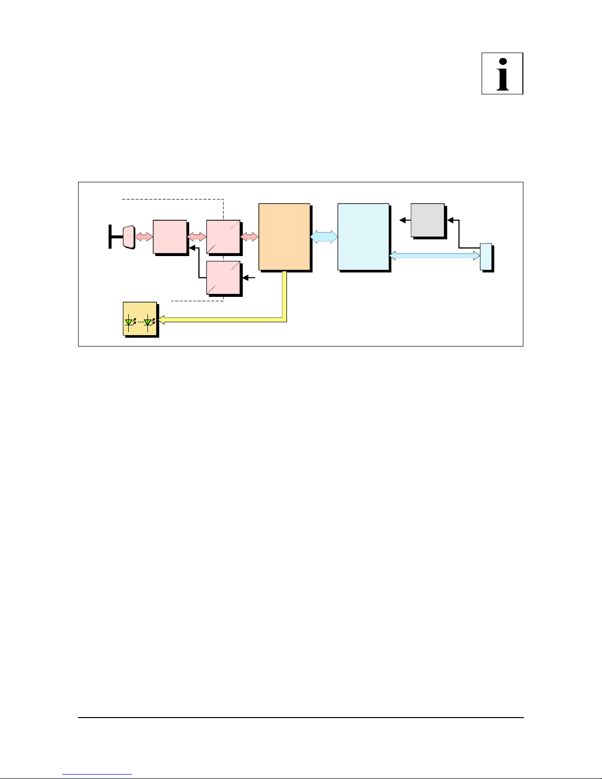
ure 1.1: Block-circuit diagram of CAN-USB/2 module
The CAN-USB/2 module is an intelligent CAN interface with an ARM LPC2292 micro controller for
local CAN data management. The module supports the USB 2.0 Hi-Speed interface with data transfer
rates of 480 Mbit/s.
The ISO 11898-compliant CAN interface allows a maximum data transfer rate of 1 Mbit/s. Like many
other features of CAN interfaces, the bit rate can be set by means of software.
CAN interface and other voltage potentials are electrically isolated by means of a digital isolater and
DC/DC converters.
The supply voltage is fed via the USB bus.
The module is equipped with four green LEDs in the front panel which indicate the current module
status.
Overview
Installation and technical Data CAN-USB/2 Rev. 1.0
4
1.2 Case View with LED and Connector Descri
p
tion
Fi
g
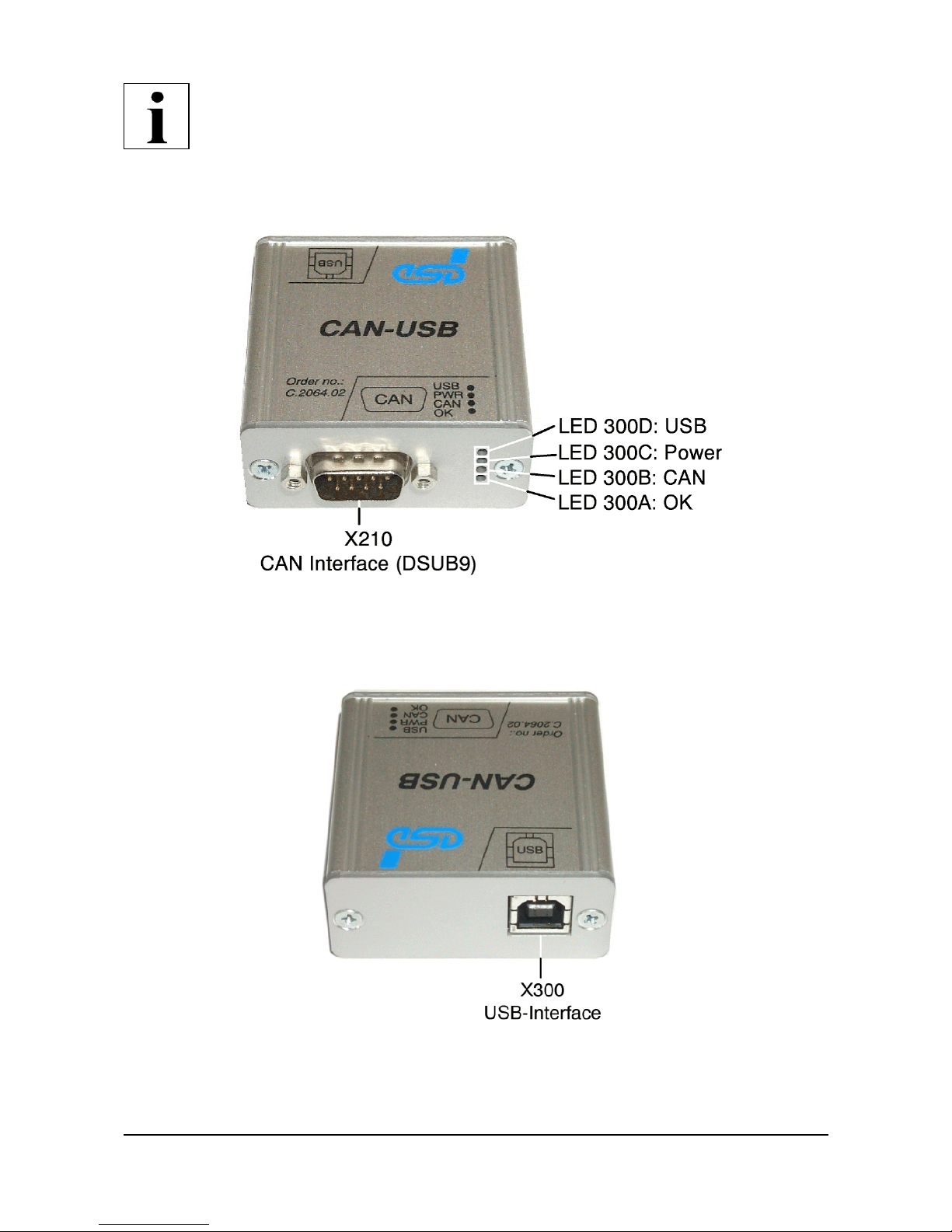
ure 1.2.1: CAN Interface and LEDs
Fi
g
ure 1.2.2: USB Interface
Overview
Installation and technical Data CAN-USB/2 Rev. 1.0 5
1.3 LED-Dis
p
la
y
s
LED NAME Status Description
LED300D USB on USB module is enumerated
(a node-ID is assigned to the USB module)
short-time
switch off
the module receives data from USB bus or
sends data on USB bus
LED300C Power on module is in operation,
the 5 V power supply is applied to the module
LED300B CAN flashes data is received or send on the CAN bus
LED300A OK on CAN interface is initialized, bit rates are set
off CAN Error occurred
Table 1.3: Description of LED display

Installation
Installation and technical Data CAN-USB/2 Rev. 1.0
6
2. Hardware Installation
Installation
p
rocedure:
1. Switch off the PC and all connected peripheral devices (monitor, printer, etc.). Additionally,
switch off all other CAN devices to whose network the CAN module is to be connected in this
procedure.
2. Connect the CAN-USB/2-module with the USB bus of the PC.
3. Connect the CAN bus to the 9-pin male DSUB connector.
Please remember that the CAN bus has to be terminated at both ends. esd offers T-connectors and
terminators. Additionally, the CAN-GND-signal has to be grounded at exactly one point in the
CAN network. Therefore the CAN termination connectors have got a grounding contact. A CAN
device whose CAN interface is not electrically isolated corresponds to the grounding of the CAN-
GND.
4. Connect your PC to mains again.
5. Switch on the PC, the peripheral devices and the other CAN bus devices.
6. End of hardware installation.
Note: The software installation is described in the manual ‘CAN-API, Installation Guide’.
Indice
Manuali Interfaccia USB popolari di altre marche

PASCO
PASCO SCIENCEWORKSHOP 750 Manuale utente

Phonic
Phonic FIREFLY 302 USB Manuale utente

OHAUS
OHAUS Scout STX Series Manuale utente

Denon
Denon DN-HC4500 - DJ Mixer USB Controller Manuale utente

Lutron Electronics
Lutron Electronics Stanza SZ-CI-USB-CPN5138 Manuale utente

Paradox
Paradox PMC5-TI00 Manuale utente


