
EUPA IEZ Manuale utente

IEZ / ITZV4
Micro-ATX Intel 810E
Micro-ATX Intel 810
Socket 370 Motherboard
User’s Guide
Model : IEZ / ITZV4
Manual Version : English, version 1.0
Release Date : JAN 14, 2000

CopyrightCopyright
CopyrightCopyright
Copyright
Copyright 2000 by this company. All rights reserved.
No part of this publication may be reproduced, transmitted, transcribed, stored in
a retrieval system or translated into any language in any form or by any means,
electronic, mechanical, magnetic, optical, manual or otherwise, without the prior
written consent of the copyright holders.
UserUser
UserUser
User¯¯
¯¯
¯sNoticeNotice
NoticeNotice
Notice
The contents of this publication are subject to change. This company reserves
the right to alter the contents of this publication at any time and without notice.
The contents of this publication may contain inaccuracies or typographical errors
and is supplied for informational use only.
Intel and Pentium are registered trademarks of Intel Corporation.
OS/2 and IBM are registered trademarks of Intemational Business Machines.
Windows and MS-DOS are registered trademarks of Microsoft Corporation.
AWARD is a registered trademark of Award Software Inc.
Other brand, corporate, and product names may or may not be registered trademarks
or copyright of their respective companies.
c

FCC & DOC Compliance
Federal communications Commission Statement
This device complies with FCC Rules Part 15. Operation is subject to the following
two conditions:
!This device may not cause harmful interference.
!This device must accept any interference received, including interference
that may cause undesired operation.
This equipment has been tested and found to comply with the limits for a Class B
digital device, pursuant to Part 15 of the FCC Rules. These limits are designed to
provide reasonable protection against harmful interference in a residential
installation. This equipment generatesm uses and can radiate radio frequency
energy and, if not installed and used in accordance with the manufacturer’s
instructions, may cause harmful interference to radio communication. However,
there is no guarantee that interference will not occur in a particular installation. If
this equipment does cause harmful interference to radio or television reception, which
can be determined by turning the equipment off and on, the user is encouraged to
try to correct the interference by one or more of the following measures:
!Re-orient or relocate the receiving antenna.
!Increase the separation between the equipment and the receiver.
!Connect the equipment to an outlet on a circuit different from that to which
the receiver is connected.
!Consult the dealer or an experienced radio/TV technician for help.
Warning! The use of shielded cables for the connection of the monitor to
the graphics card is required to assure compliance with FCC regulations
Changes or modifications to this authority to operate this equipment.

CONTENTS
General Description
Manual Features / Package Check List........................................................I
SECTION 1: PRODUCT INFORMATION
1-1 Mainboard Specifications..............................................................1-2
1-2 Mainboard Layout..........................................................................1-3
SECTION 2: HARDWARE INSTALLATION
2-1 Jumper Settings.............................................................................2-1
2-2 Connectors....................................................................................2-3
2-3 Game / Audio Connector...........................................................2-7
2-4 System Memory Installation................................................................2-8
SECTION 3: CMOS SETUP UTILITY
3-1 BIOS Setup Main Menu.....................................................................3-1
3-2 Standard CMOS Setup......................................................................3-2
3-3 Adcanced BIOS Features.........................................................................3-4
3-4 Advanced Chipset Features .............................................................3-8
3-5 Integrated Peripherals................................................................3-11
3-6 Power Management Setup........................................................... 3-15
3-7 PnP/PCI Configurations.......................................................3-18
3-8 PC Health Status......................................................................... 3-19
3-9Frequency/Voltage Control.............................................................. 3-19
3-10 Load Fail-Safe Defaults.....................................................................3-21
3-11Load Optimized Defaults..............................................................3-21
3-12 Set Supervisor/Use Password.....................................................3-22
3-13 Save & Exit Setup...................................................................3-22
3-14 Exit Without Saving...........................................................................3-22
SECTION 4: SOFTWARE UTILITY
4-1 VIA V x D Setup Program.....................................................................4-1
4-2 VIA Audio Setup Program...................................................................4-1
4-3 VIA Chipset Driver Setup Program........................................................4-2
4-4 VIA Hardware Monitor System V1.05....................................................4-2

Manual FeaturesManual Features
Manual FeaturesManual Features
Manual Features
This manual is divided into the following four sections:
Section 1: Product InformationSection 1: Product Information
Section 1: Product InformationSection 1: Product Information
Section 1: Product Information
A brief overview of what comes in the mainboard package, the mainboard layout an the
specification it appears.
Section 2: Hardware InstallationSection 2: Hardware Installation
Section 2: Hardware InstallationSection 2: Hardware Installation
Section 2: Hardware Installation
Tell you the usage of the mainboard jumpers and the connectors.
Section 3: CMOS Setup UtilitySection 3: CMOS Setup Utility
Section 3: CMOS Setup UtilitySection 3: CMOS Setup Utility
Section 3: CMOS Setup Utility
A summary of the mainboard CMOS (BIOS) Setting.
Section 4: BIOS / Software UtilitySection 4: BIOS / Software Utility
Section 4: BIOS / Software UtilitySection 4: BIOS / Software Utility
Section 4: BIOS / Software Utility
Introduction of some useful mainboard BIOS / Software utility.
Package Check ListPackage Check List
Package Check ListPackage Check List
Package Check List
This IEZ / ITZV4IEZ / ITZV4
IEZ / ITZV4IEZ / ITZV4
IEZ / ITZV4 mainboard package contains the following items. Please inspect the
package contents and confirm that every thing is there. If anything is missing or damaged,
call your vendor for instructions before operating.
The Package includes:
!One IEZ / ITZV4IEZ / ITZV4
IEZ / ITZV4IEZ / ITZV4
IEZ / ITZV4 mainboard
!One Floppy Interface Cable
!One IDE Interface Cable
!One Motherboard Resource CD
General DescriptionGeneral Description
General DescriptionGeneral Description
General Description
Thanks for purchasing IEZ / ITZV4 Socket 370IEZ / ITZV4 Socket 370
IEZ / ITZV4 Socket 370IEZ / ITZV4 Socket 370
IEZ / ITZV4 Socket 370 mainboard. IEZIEZ
IEZIEZ
IEZ is
based on Intel 810E
chipset (North Bridge FW82810E & South Bridge FW82801AA). The 810E chipset provides
stability and value with Intel graphics performance and smart integration. ITZV4ITZV4
ITZV4ITZV4
ITZV4 chipset
is Intel 810(North Bridge FW82810 & South Bridge FW82801AA). It is a highly integrated
chipset designed for the basic graphics / multimedia PC platform. IEZ / ITZV4IEZ / ITZV4
IEZ / ITZV4IEZ / ITZV4
IEZ / ITZV4
provide you perfect function to be the same with your system operation and end user.
This user’s manual contains all the information and features that show you how to use
the IEZ / ITZV4IEZ / ITZV4
IEZ / ITZV4IEZ / ITZV4
IEZ / ITZV4 motherboard. Please take a moment to familiarize yourself with the design
and organization of this manual.
IEZ / ITZV4 Motherboard User’s Manual
I

SECTION 1
P
Product InformaProduct Information
Product Information
1-1 Mainboard Specifications
IEZ / ITZV4 Motherboard User’s Manual
1-1
I Product Information
Form Factor Micro ATX form factor
Board Size 24.4cm x 19.0cm
CPU Supports Socket 370 CPU--Celeron(PPGA) & Coppermine(FC-PGA)
Supports FSB 66.8/73/100/103/118/124/133/137/140/150MHz
Supports CPU type/clock by jumperless BIOSset up
System Memory DIMM 168-pin x 2, SDRAM maximum 512MB
Chipset
Intel 810 / 810E Chipsets including:
-Intel 82810(ITZV4) / Intel 82810E(IEZ)--GMCH
-Intel 82801AA ICH
-Intel 82802AB FWH
Expansion Slots 3 x PCI slots
1 x ISA slot
1 x AMR connector for MC'97
Serial Port Two serial ports UATR 16550 compatible
Parallel Port
One parallel port supports:
-SPP-standard parallel port
-EPP-enhanced parallel port
-ECP-extemded capabilities port
Floppy Interface Support drivers inches/format with:
-3.5 inches-720KB/1.44MB/2.88MB
-5.25 inches-360KB/1.2MB
Ide Interface Dual Ide Interface support 4 x IDE HDD or CDROM
Support PIO Mode 4, ULTRA DMA/33 & ULTRA DMA/66
USB Port Two USB ports supported
Support USB Legacy Keyboard function
PS/2 Mouse PS/2 mouse supported by connector onboard
PS/2 Keyboard PS/2 Keyboard supported by connector onboard
Sound Function ON-ICH Audio Codec AC'97
Fuse Support Recoverable fuse for USB,KB & MOUSE
RTC and Battery Built in ICH
Lithium(CR-2032) battery
Power Connector ATX
Wake up Function LAN wake up
RTC Alarm wake up
Hardware Monitor
3 Fan speed Monitor
4 Positive Voltage Inputs, 2 intrinsic voltage monitoring
Over temperature indicate output
Automatic Power on voltage detection beep
BIOS
Award BIOS
Supports APM, DMI and ACPI
Supports STR(Suspend To RAM)
Supports virus warning
Supports Flash / Upgrade BIOS functions
LED Indicator System Power LED
HDD activity LED
System Suspend LED
1-21-2
1-21-2
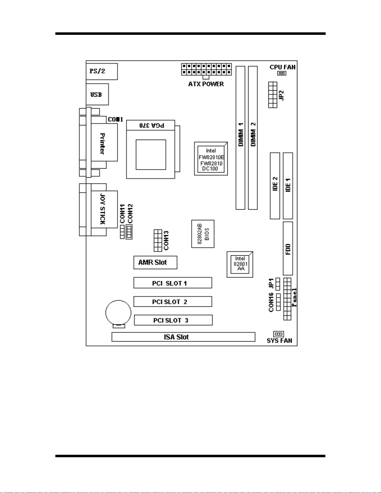
1-2 Motherboard LayoutMotherboard Layout
Motherboard LayoutMotherboard Layout
Motherboard Layout
I Product Information
IEZ / ITZV4 Motherboard User’s Manual
1-2
JumpersJumpers
JumpersJumpers
Jumpers
1. JP2 CPU Clock Frequency
2. JP1 ClearCMOS
3. CON13 COM2
4. CON16 IrDA
5. CON11,CON12 CD_IN

Expansion SocketsExpansion Sockets
Expansion SocketsExpansion Sockets
Expansion Sockets
1. DIMM1 Support 168-pin DIMM Memory
2. DIMM2 Support 168-pin DIMM Memory
Expansion SlotsExpansion Slots
Expansion SlotsExpansion Slots
Expansion Slots
1. CPU Socket 370 CPU
2. PCI slot1 to slot3 32-bit PCI Bus Expansion slot
3. ISA slot ISA Bust Expansion slot
3.AMRAMR Expansion Slot for MC97 Devices
ConnectorsConnectors
ConnectorsConnectors
Connectors
1. IDE1 Primary IDE Connector
2. IDE2 Secondary IDE Connector
3. Floppy Floppy Drive Connector
4. Panel - PowerOn ATX Power on
- Reset Reset Swithch Connector
- HDD Led HDD Led Connector
- Power Led ATX Power Led Connector
- Speaker Chassis Speaker Connector
- KEYLOCK Keyboard Lock Switch Connector
5. Sys Fan System Fan Connector
6. CPUFan CPU Fan Connector
7. ATX Power ATX Power Connector
8. COM2 COM2 Connector
9. CD Audio CD-IN Connector
10. Joystick Game / Audio Connector
11. Printer Ptinter (Parallel) Port Connector
12. USB Universal Serial Bus Port1 and Port2
13. PS/2 Mouse PS/2 Mouse & Keyboard Connectors
IEZ / ITZV4 Motherboard User’s Manual
1-3
I Product Information

SECTON 2
HARDWARE INSTALLATION
This section gives you a step-by step procedure on how to install your system. Follow each
section accordingly.
2-1 Jumper Settings
Please refer the following figures for the locations of the jumpers on the mainboard.
2-1.1 CMOS Clear Setting
JP1 Clear CMOS
Clear CMOS Normal
(Default)
To clear CMOS,please follow the steps below:
1. Power off the system and unplug the chassis AC power cord.
2. Short JP1 at pin 2-3 for few seconds.
3. Set JP1 back to its Normal position at pin 1-2.
4. Plug the AC power cord to the chassis.
5. Power on the system and load the BIOS setup default.
IEZ / ITZV4 Motherboard User’s Manual
2-1
2-1.2 CPU Type Setting
Static Precautions
Static electricity can be a serious damage to the electronic components on this mainboard.
To avoid damage caused by electrostatic discharge, observe the following precautions:
- Don’t removes the motherboard from its anti-static packaging until you are ready to
install it into a computer case.
- Before you handle the motherboard in any way, touch a grounded, antistatic surface,
such as an unpainted portion of the system chassis, for a few seconds to discharge
any built-up static electricity.
- Handle add-in cards and modules by the edges or mounting bracket.
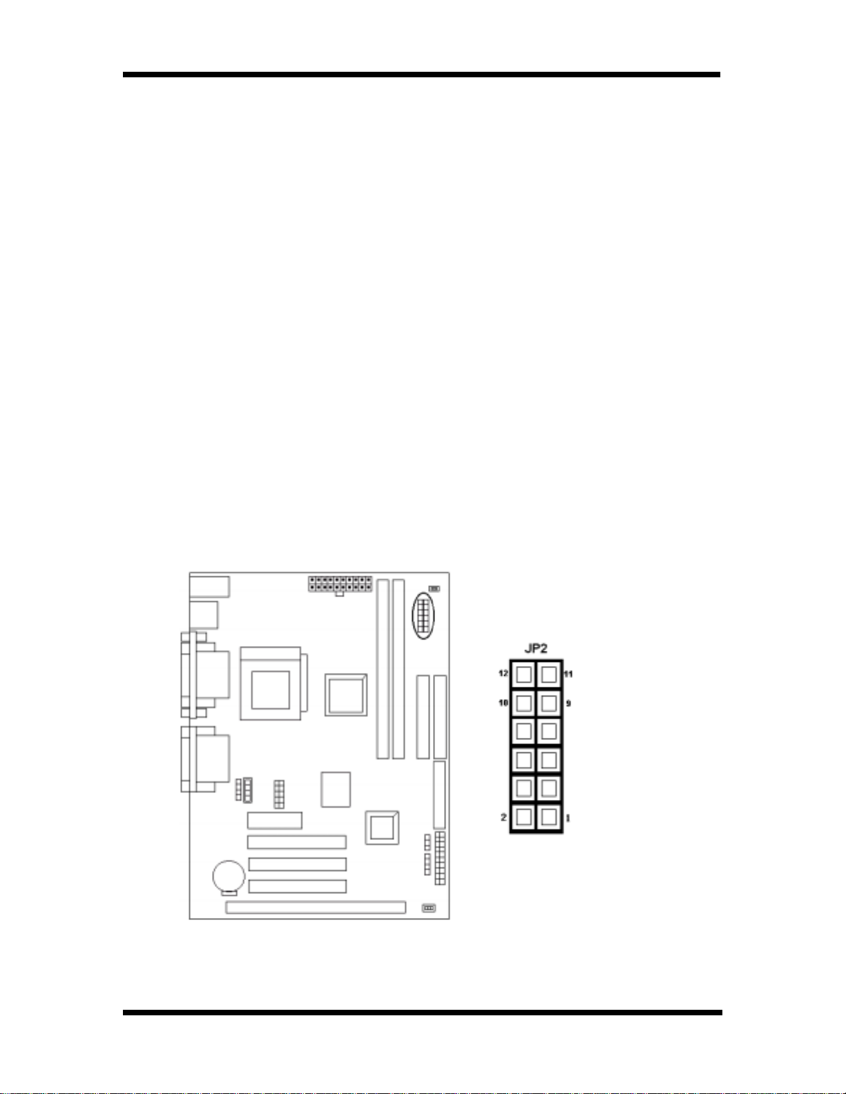
CPU Setting
After installing the CPU, you must set the clock selection jumpers to match the frequency of
the CPU. Find the jumpers labeled JP2 set the jumpers (from 1 to 8 jumpers, we call them as
FS0, FS1, FS2 and FS3) according to the figure below and table for CPU frequency. JP2’ s
jumpers from 9 to 12 (we call them as FS4 and FS5) are used for over-clock, we also
recommend them to users.
II. HARDWARE INSTALLATION
""
""
"
CPU Frequency
IEZ / ITZV4 Motherboard User’s Manual
2-2
FS0
FS1
FS2
FS3
FS4
FS5
Questo manuale è adatto per i seguenti modelli
1
Indice
Altri manuali EUPA Scheda madre


Manuali Scheda madre popolari di altre marche


Telit Wireless Solutions
Telit Wireless Solutions SL869-3DR Manuale utente

Gigabyte
Gigabyte GA-9IVDT Manuale utente

Texas Instruments
Texas Instruments ADS8372EVM Manuale utente

Commell
Commell MS-C73 Manuale utente

IBT Technologies
IBT Technologies MB860 Manuale utente

Nvidia
Nvidia TEGRA DG-04927-001_V01 Manuale utente


