Evoqua Wallace & Tiernan W3T170339 Manuale utente

WALLACE & TIERNAN®SENSOR MEASURING MODULES
AND RETROFIT KITS FOR MFC
INSTALLATION MANUAL

2WT.050.580.001.DE.IM.0714
Sensor measuring modules for MFC

Sensor measuring modules for MFC Contents
3
Contents
1. Introduction 5
1.1 Documentation 5
1.1.1 Target groups 5
1.2 Conventions 5
2. General safety instructions 7
2.1 Intended use 7
3. Description 9
3.1 Version 9
3.1.1 Sensor measuring modules 9
3.1.2 Plug in cards for retrofit kits 9
3.2 Description 10
3.2.1 General 10
4. Installation 13
4.1 Opening the housing 13
4.2 Installing and wiring plug-in card 1 to 7 15
4.3 Installing IR board 18
4.4 Connecting the sensor cable 19
4.5 Inserting and connecting the sensors 20
4.6 Mounting the housing covers 22
4.7 Switching the unit on 22
4.8 Firmware update 23
4.8.1 lAP download description 24
5. Wiring Diagram 27
6. Index 35

4WT.050.580.001.DE.IM.0714
Contents Sensor measuring modules for MFC
Sensor measuring modules for MFC Introduction
1.
5
1. Introduction
1.1 Documentation
1.1.1 Target groups
This documentation provides installation and
maintenancepersonnel with the information needed to install and
retrofit the unit.
All persons working with thesensor measuring module and retrofit
kits must have read and understood the instruction manual,
particularly the safety instructions.
1.2 Conventions
Please note
The different weighting assigned to the various notes in this
manual is indicated by means of pictogram symbols.
Icon Note Signification
Danger! Imminent danger to life and limb;
failure to remedy the situation will
lead to serious or fatal injury.
Warning! Danger to life and limb; failure to
remedy the situation may lead to
serious or fatal injury.
Caution! Failure to observe this information
may lead to moderately serious or
minor injury or material damage.
Warning! Danger of electric shocks.
6WT.050.580.001.DE.IM.0714
Introduction Sensor measuring modules for MFC
1.
Please note These notes facilitate work with the
unit.
Icon Note Signification

Sensor measuring modules for MFC General safety instructions
2.
7
2. General safety instructions
2.1 Intended use
Thesensor measuring modulesand retrofit kitsare designed tobe
installed in the MFC control unit.
The operational safety of the sensor measuring modules and
retrofit kits can onlybe guaranteed solong as they are used strictly
as intended. They may only be used for the purpose defined in the
order and under the operating conditions indicated in the
technical specifications. Modifications to the sensor measuring
module and retrofitkits which go beyond those described in this
manual are not permitted.
Compliance with the intended use also includes reading this
instruction manual and observing all the instructions it contains.
The operator bears full and sole responsibility if this unit is put to
any use which does not comply strictly and exclusively with this
intended use.

8WT.050.580.001.DE.IM.0714
General safety instructions Sensor measuring modules for MFC
2.
2.2 General safety instructions
Evoqua Water Technologies GmbH places great emphasis on
safety when work is performed using the sensor measuring
modules and retrofit kits. Safety is our guiding principle right from
the design phase; the system is therefore equipped with safety
features.
Safety instructions The safety instructions in this documentation must be observed
unconditionally at all times. Additional industry-wide or in-house
safety regulations also continue to apply.
State-of-the-art technology The sensor measuring modules and retrofit kits were constructed
in accordance with the state of the art and all recognized technical
regulations relevant to safety. However, if the unit is used by
untrained personnel, potentially fatal hazards may occur for the
user or third parties during use of the unit, and damage to the
sensor measuring modules, retrofit kits and other equipment may
also result.
Worknotspecifically describedin this instructionmanualmayonly
be performed by authorized personnel.
Personnel The operator running the systemmust ensure that only authorized
and qualified specialists work with and on the system and only
within their assigned areas of responsibility. "Authorized
specialists" refers to trained technicians of the operator, Evoqua
Water Technologies GmbH and, if applicable, the service partner.
Only qualified electricians may perform work on electrical
components.
Spare parts / components Correct operation of the sensor measuring modules and retrofit
kits is only guaranteed if original spare parts and components are
used in the combinationdescribed in this Operating Manual. If this
stipulation is not observed, there is the risk of malfunction or
damage to the sensor measuring modules and retrofit kits
Extensions and conversions The system must not, without the express, prior, written consent of
the manufacturer, be modified, extended, or converted in any way
that might adversely affect its safety.
Electrical power During normal operation, the MFC must remain closed.
Switch off the complete system and secure against reactivation
prior to installation, inspection, maintenance and repair work.
Connect cables in accordance with the terminal diagrams.
Please note
For more information, including the general safety instructions,
please review the instruction manual „MFC”.

Sensor measuring modules for MFC Description
3.
9
3. Description
Due to the MFC's modular design, simple retrofitting and
configurationof sensormeasuringmodules in accordancewith the
plug-and-play principle is possible at any time.
Different versions are available.
3.1 Version
3.1.1 Sensor measuring modules
W3T170339 Total chlorine TC1
W3T170341 Total chlorine TC1-S
W3T170343 Free chlorine FC1
W3T170345 Chlorine dioxide CD7
W3T170347 Ozon OZ7
W3T166292 pH
W3T166165 Redox
W3T166293 Fluorine (F-)
W3T158763 Conductivity 600 µS
3.1.2 Plug in cards for retrofit kits
W3T158761 Cl2- DEPOLOX®5
W3T158762 Cl2- DEPOLOX®4 (PT100)
W3T166161 mA/V input
W3T166162 4x mA output
W3T170020 Relay (eight-way)
W3T166240 Infrared interface
10 WT.050.580.001.DE.IM.0714
Description Sensor measuring modules for MFC
3.
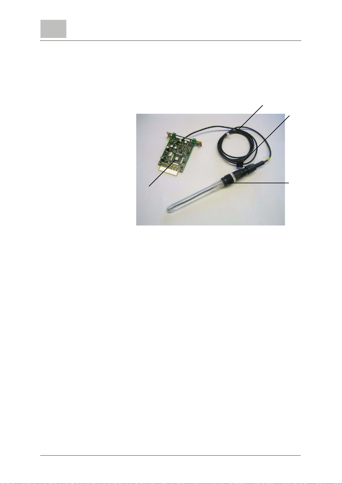
3.2 Description
3.2.1 General
A Sensor cable
B Housing duct
C Sensor
D Plug-in card
Sensor measuring module The sensor measuring module consists of:
• Sensor (C) (not in 3 electrode cells,
mA/V input)
• Sensor cable (A) with watertight housing cable
duct (B) (not in 3 electrode cells,
mA/V input)
• The pre-calibrated plug-in card (D)
Due to the MFC's modular design, simple retrofitting and
configurationof sensormeasuringmodules in accordancewith the
plug-and-play principle is possible at any time.
A
B
C
D
Questo manuale è adatto per i seguenti modelli
14
Indice
Altri manuali Evoqua Unità di controllo


Manuali Unità di controllo popolari di altre marche

Festo
Festo Compact Performance CP-FB6-E Manuale elenco delle parti

Elo TouchSystems
Elo TouchSystems DMS-SA19P-EXTME Manuale utente

JS Automation
JS Automation MPC3034A Manuale utente

JAUDT
JAUDT SW GII 6406 Series Guida rapida

Spektrum
Spektrum Air Module System Manuale utente

BOC Edwards
BOC Edwards Q Series Manuale utente


