
Faber Blokhus Manuale utente

Installation manual
Blokhus
(Extension modules & HE-module)
ENG
40011609-2012

Installation manual Blokhus (Extension modules & HE-module)
1 < <<<

Installation manual Blokhus (Extension modules & HE-module)
2 < <<<
Installation manual Blokhus (Extension modules & HE-module)
3 < <<<
1.0
1.1
1.2
1.3
1.4
1.5
1.6
A
B
C

Installation manual Blokhus (Extension modules & HE-module)
4 < <<<
1.7
1.8a
1.8b

Installation manual Blokhus (Extension modules & HE-module)
5 < <<<
1.9
2.0
2.1
2.2
2.3
2.4
F

Installation manual Blokhus (Extension modules & HE-module)
6 < <<<
1Dear user
Congratulations on your purchase of a Faber fire! A
quality product from which you will experience
warmth and atmosphere for many years. We
recommend that you read this manual carefully
before using the fireplace. If any problem arises
despite our strict quality control, you can always
contact your dealer or Glen Dimplex Benelux B.V.
For any warranty claims, it is essential you first
register your fireplace. During this registration,
you’ll find all information regarding our warranty.
Please note!
The details of your fireplace can be found in
the user manual.
You can register your fire at: www.faberfires.com
Glen Dimplex Benelux B.V.
Address: Saturnus 8
NL-8448 CC
Heerenveen
Tel: +31 (0)513 656 500
Info: www.faberfires.com
1.1 Introduction
Installation and maintenance of the appliance must
be carried out by a professional with proven
knowledge and competence. A professional takes
into account all technical aspects such as heat
radiation and gas connection as well as flue gas
exhaust requirements.
Where the installation instructions are not clear,
national/local regulations must be followed.
1.2 Check
Check the fireplace for transport damage and
immediately report any damage to your supplier.
1.3 CE Declaration
We hereby declare that Glen Dimplex Benelux B.V.
released Faber gas-atmosphere heating appliance
by its design and construction method complies
with the Regulation (EU): 2016/426 and (EU)
2015/1188.
Product: gas room heater
Model: Blokhus
This declaration will become null and void as soon
as the unit is in any way modified without written
authorization of Glen Dimplex Benelux B.V.
2Safety instructions
Please note!
It is advisable to always install a screen for the
fireplace if children, elderly or disabled people are
present in the same room as the fireplace. If
regularly vulnerable persons can be present in the
room without supervision, sufficient protection
must always be placed around the fireplace.
This appliance must be installed according
with the rules in force and used only in a
sufficiently space.
The appliance must be checked annually
in accordance with this installation
manual and the applicable national and
local regulations.
Ensure that the data on the type label
matches the local gas type and pressure.
The appliance is designed for atmosphere
and heating purposes. This means that all
visible surfaces, including the glass, can
become hotter than 100°C. An exception
by free standing models is the underside
of the fireplace and the control buttons.
Do not use the remote control and / or
app outside the room where the fire is
located. So that you are always aware of
the situation around the fireplace when it
is being operated.
The settings and the construction of the
fireplace must not be changed!
Do not place extra imitation wood or
other material on the burner or in the
combustion chamber.
Do not place any combustible materials
within 0,5m of the radiation area of the
fire.
Through the natural air circulation of the
fireplace moisture and uncured volatile
components from paint, building
materials and carpeted floors, etc. are
attracted. These parts can settle as soot
on cold surfaces. Therefore do not light
the fireplace shortly after installation.
2.1 Using the fire for the first time
Provide extra ventilation and open all the windows
of the room during the initial start-up of the fire.
Let the fire burn at the highest setting for a few
hours so that the paint gets the chance to harden
and any released vapours are safely removed. Keep
vulnerable people and pets out of this room during
this process.

Installation manual Blokhus (Extension modules & HE-module)
7 < <<<
3Installation requirements
3.1 Appliance
This appliance may not be installed in a
chlorine-containing environment. (Pools
etc.).
When using the extension modules, keep
a minimum distance of 250 millimeters to
the ceiling.
Minimal distance to combustible
materials:
oRear side 20mm;
oFront 500mm;
oSides 500mm;
oUnder side 484mm.
3.2 Discharge and outlet requirements
First, carry out a flue calculation (see chapter 11)
and place the right flue restrictor before installing
the outlet! (Generally a 30mm flue restrictor is
installed).
For supply and discharge always use the
prescribed and to be supplied Faber flue
materials. Please contact Glen Dimplex
Benelux B.V.. Only with use of these
materials Faber can guarantee proper
performance.
The distance to combustible materials
must be min. 50mm, calculated from
outside of the flue material (EN 1856-1
T600 N1 D Vm –L20040 O(50)).
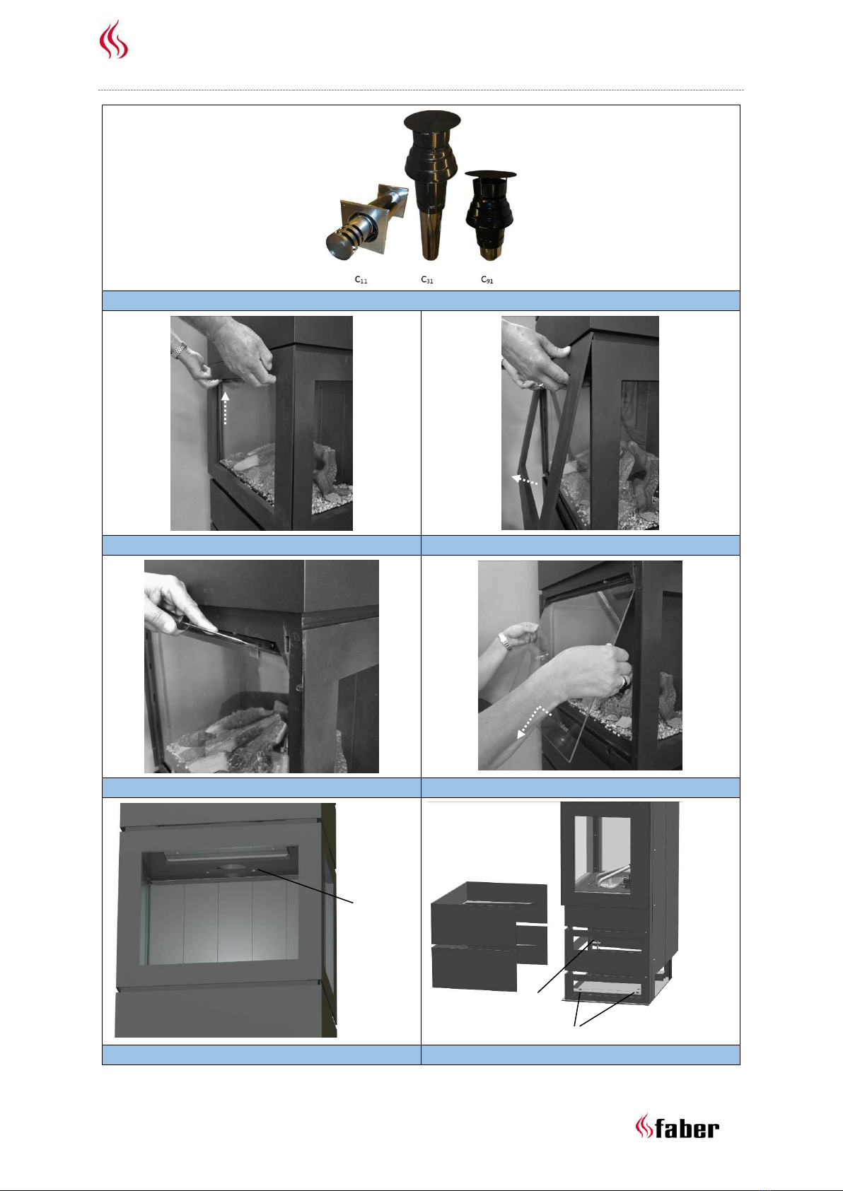
Outlets (fig. 1.0)
The balanced flue pipe for combined air supply and
discharge can use a wall terminal or a roof
terminal. Verify that the desired outlet meets the
local regulations regarding pollution and
ventilation openings.
Please note!
For proper functioning, the outlet must at
least be 0,5m away from:
Corners of the building;
Roof overhangs and balconies;
Roof edges (with the exception of the
ridge edge, see chapter 15).
C11, outlet via facade
Through a wall or façade, use a Faber wall outlet.
Depending on the flue calculation this can be
100/150mm or 130/200mm.
C31, outlet via roof
For a (flat) roof, use a Faber roof outlet with a
diameter of 100/150mm.
C91, existing chimney
For an existing chimney, use a Faber chimney
outlet with a diameter of 100/150mm.
In this case the existing chimney acts as air inlet an
inserted flexible stainless steel pipe discharges the
flue gas. The top (Faber chimney cover plate) and
the bottom (Faber chimney connection set) should
be airtight.
Depending on the calculated flue diameter, you
must use a flexible stainless steel pipe of
Ø100mm (article number AJ005503) or Ø130mm
(article number AJ005603) as specified by Faber.
For this, contact Glen Dimplex Benelux B.V.
Please note!
The minimum chimney diameter for a
130mm flexible stainless steel pipe must
be 200x200mm and for a 100mm flexible
stainless steel pipe and 150x150mm.
Don’t connect more than one fire at the
existing chimney.
The chimney must be in good condition:
oNo leakage;
oWell cleaned.
For more information about the connections to
existing chimney ducts, please request the
installation instructions “Chimney Connection Set”.
4Preparation and installation
instructions
4.1 Gas connection
The gas connection must comply with the
applicable local standards.
Please note!
Calculate the gas pipe so that no pressure
drop occurs.
We advise using a gas connection directly from the
gas meter to the appliance (see dimensional
drawing 17.2), with a shut-off valve in the
proximity of the appliance, which must always be
freely accessible.

Installation manual Blokhus (Extension modules & HE-module)
8 < <<<
4.2 Electrical connection
Install a 230VAC/50Hz wall socket near the
fireplace for connecting the control unit.
See fig. 1.8a for the wiring diagram of the Blokhus:
A= Adapter (6V)
B = LED Symbio-Module
C = Receiver
D = Ignition pin
E = Gas valve
See fig. 1.8b for the wiring diagram of the Blokhus
with I.T.C.:
A= Adapter (6V)
B = LED Symbio-Module
C = Receiver
D = Ignition pin
E = Gas valve
F = I.T.C. (Intelligent Technical Controller)
4.3 Smart Home installation
Please note!
This is only possible if the fire is equipped
with I.T.C!
The controller can be connected to an external
source, such as a Domotica system, by using a
Faber Interface Unit (article number A9323000).
4.4 Preparing the fireplace
Remove the fireplace from its packaging.
To do this unscrew the nut and bolt at the
bottom of the appliance.
Remove the front glass (see chapter 5)
and any mouldings, store them at a safe
place and remove the packaged parts
from the fireplace.
The included wall bracket (fig 1.9) is only
for use with the optional extension
module(s). See chapter 19 until 21.
Prepare the gas connection on the gas
valve.
If necessary, the lower and upper panel
can be removed. To do this, loosen the 2
bolts on the inside, lift the panel slightly
so that it can be moved forward (fig. 1.6-
B). The middle panel is already loose. This
is the access for the gas control unit.
4.5 Positioning the fireplace
Take into account the installation requirements
(see chapter 3). Place the fireplace at the right
place and level it.
Please note!
The fireplace can be levelled with the 4
adjustable feet in the bottom plate (see fig.
1.6-C). Use an Allen key 5 for this.
A wall bracket is supplied as standard with the
appliance, see fig. 1.9. Only use these in
combination with the optional extension modules,
see chapter 19.
4.6 Installing the flue pipes
Install the flue pipes according to the installation
manual supplied with the appliance (40011968)!
For fitting the flue pipe on the fire the top
plates can be removed (fig. 1.7).
The distance to combustible materials
must be min. 50mm, calculated from the
outside of the flue pipe.
Never start immediately with length-
adjustable concentric flue pipe on the
appliance.
Horizontal sections should be installed to
allow a slope towards the appliance
(3 degrees).
Built the system from the appliance. If this
is not possible you can make use of an
extendable adapter section.
For fitting of the flue system, the 0,5m
length-adjustable pipe must be used.
Make sure that the inner pipe is always
15mm longer than the outer pipe. Wall-
and roof terminal can also be cut. These
components must be secured with a self-
tapping screw.
Options:
For the installation instructions of the
optional extension modules and the HE-
module in combination with the flue pipes
see chapter 19 until 21.
Please note!
Only 1 HE-module may be used!

Installation manual Blokhus (Extension modules & HE-module)
9 < <<<
5Removing glass
5.1 Front glass
Remove the front panel. This is possible
by slightly lifting the panel and pulling the
bottom towards you (fig. 1.1 and 1.2).
Remove all glass clamps (fig. 1.3).
Remove the front glass. (fig. 1.4).
For replacing the glass repeat the steps in reverse
order.
Please note!
Avoid fingerprints on the glass, these are no
longer removable once the fire is used.
5.2 Side glass
For cleaning only it’s not necessary to remove the
side glass.
Remove the front glass (see chapter 5.1);
Remove the log set;
Remove the 2 log set supports (fig. 2.1);
Remove the burner plate (fig. 2.2);
Place a suction cup;
Remove the 4 glass clamps (fig. 2.3);
Remove the side glass (fig. 2.4).
For replacing the glass repeat the steps in reverse
order.
Please note!
Avoid fingerprints on the glass, these are no
longer removable once the fire is used.
6Placing decoration material
It is not permitted to use other or to add more
material in the combustion chamber.
See the supplied decoration instruction card in
chapter 18:
Place the glass panel (fig. 2.0 F) on the
bottom in the gaps left and right.
Spread the glass granulate over the glass
panel (one layer) and cover these with
part of the supplied vermiculite granules
(the amount of vermiculite granules
affects the intensity of the glow effect and
can be done according to your own
discretion);
Place the log set. Make sure that the logs
are properly connected to the tube
burners and rest on the bottom of the
fire. Remove the glass granulate and
vermiculite granules underneath these
logs.
Divide the ash material between the logs,
don’t cover the air intake (the perforated
parts at the back).
Please note!
Keep the pilot flame free from glass granulate
and ash material!
Start the fireplace as described in the user
manual.
Assess whether the flame distribution and
if present, the Symbio effect (glow bed), is
good. Move or remove any glass granulate
/ ash material to create a nice glow bed.
Install the front glass and check the fire
image.
7Checking the installation
Checking for gas leaks
Check with a gas leak finder all connections and
pipes for gas leakage.
Check primary- and burner pressure
Check if the inlet pressure correspond to the data
on the rating plate.
Measuring the inlet pressure:
Close the shutoff valve. Turn the
measuring nipple “A” (fig. 1.7) a few turns
to open and connect a measuring hose to
the gas valve.
Take this measurement when the
fireplace runs at high and low settings.
Do not use the device if the inlet pressure
deviates (+20% or -20%).
Measuring the burner pressure:
Check the burner pressure only with proper inlet
pressure.
Turn measuring nipple “B” (fig. 1.7) some
turns open and connect a measuring hose
to the gas valve.
The pressure must correspond to the
value indicated in the technical
specifications of this manual. In case of
deviation contact the manufacturer.
Please note!
Close both pressure measuring nipples and
check for gas leakage.
Check ignition and burner
Ignite the fireplace by using the remote control as
described in the user manual and test all burner
possibilities.
Indice
Manuali Unità di controllo popolari di altre marche

Festo
Festo Compact Performance CP-FB6-E Manuale elenco delle parti

Elo TouchSystems
Elo TouchSystems DMS-SA19P-EXTME Manuale utente

JS Automation
JS Automation MPC3034A Manuale utente

JAUDT
JAUDT SW GII 6406 Series Guida rapida

Spektrum
Spektrum Air Module System Manuale utente

BOC Edwards
BOC Edwards Q Series Manuale utente


