Fluigent ESS Manuale utente

USER’S
MANUAL
EASY
SWITCH
SOLUTIONS
MICROFLUIDIC VALVES

WARNINGS
Do not place the product in an unstable location with a level surface
and a strong and stable support
Do not use other power supply than the one provided with the ESSTM
The power supply provided with the ESSTM has been carefully selected
to meet the power requirements of the ESSTM in all configurations and
to comply with all safety standards.
If you are using the ESSTM platform with other flow control systems,
please check that the pressure in your fluidic system does not exceed
100 psi.
Aria is a perfusion system which automates perfusion or timed
injection protocols. It allows for the sequential delivery of up to 10
different solutions at the desired flow rate into a microfluidic chip,
perfusion chamber or petri dish.
Do not open SWITCHBOARD, 2-SWITCHTM, M-SWITCHTM or L-SWITCHTM
devices. Please refer all servicing to after-sales service department
(support@fluigent.com)
Prevent any objects or liquid from entering the SWITCHBOARD,
this may cause a short-circuit failure or other malfunction. Failing to
respect this advice would:
• Expose you to direct current/voltage in case the device is under
voltage which may lead to severe damages
• Void device's warranty
• Discharge our company from any liability regarding physical or
device damages.

INTRODUCTION
Fluidic circuits examples
2SWITCHTM VALVE
Fluidic principle
Product overview
Fluidic connections
Positionning
MSWITCHTM VALVE
Fluidic principle
Product overview
Fluidic connections
Positionning
LSWITCHTM VALVE
Fluidic principle
Product overview
Fluidic connection
Positionning
SWITCHBOARD
Product overview
Connection
HOW TO USE ESSTM WITH GAS
HOW TO START WORKING WITH THE ESSTM
FREQUENTLY ASKED QUESTIONS
TECHNICAL SPECIFICATIONS
SERVICING & WARRANTY
SUMMARY
4
6
5
5
6
7
8
9
9
10
11
12
13
13
14
15
16
17
17
18
19
20
21
22
23
4
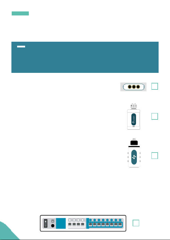
The Easy Switch SolutionTM platform (ESSTM) provides solutions for path
selection in microfluidics. The Easy Switch SolutionsTM platform enables
one to implement 3 different kind of valves in a microfluidic circuit.
INTRODUCTION
1. The 2-SWITCHTM is a 3-port/2-position
solenoid valve: 2 ports can alternatively be
connected to a third one.
2. The M-SWITCHTM is a 11-port/10-position
rotary valve: 10 peripherical ports connected
to a central one.
3. The L-SWITCHTM is a 6-port/2-position valve
to inject precise volume of fluid or for switching
fluid to different channels.
4. The SWITCHBOARD is a hub that hosts up to 4 M-SWITCHTM or 4
L-SWITCHTM and up to 8 2-SWITCHTM. The device allows communication
between the PC with dedicated software : ESSTM Control for live control
or Microfluidic Automation Tool (MAT) to automate protocols, plus it
ensures power supply to the connected valves.
1
2
3
4

5
Combining the 2-SWITCH™, M-SWITCH™ and L-SWITCH™ valves
using the SWITCHBOARD allow one to access new possibilities to easily
design and build even the most complex microfluidic circuits. It is also
a powerful tool to simplify chip design and automate experiments.
INTRODUCTION
The ESS™ platform has been designed to work at its best
performances with FLUIGENT pressure-based flow control solutions
(LineUpTM series MFCS™ series and Flow-Rate Platform).
It is however possible to use the ESS™ platform with other flow
control systems provided that the pressure applied to the ESS™
devices does not exceed 7 bar (~ 100 psi)
Note: To ensure product longevity, the M-SWITCHTM should not be
used with an operational pressure above 5 bar (~72,5 psi)
The ESS™ user manual explains how to use the ESS™ series for
ones daily work. It will describe all the ESS™ functionalities that will
help rationalize microfluidic circuits and automate any experiments.
Examples of applications using the ESS™ are also described as well
as answers to the frequently asked questions about the ESS™. With
these elements one will be able to exploit fully the performance of the
Easy Switch Solutions™ platform for dedicated application.

6
INTRODUCTION
F
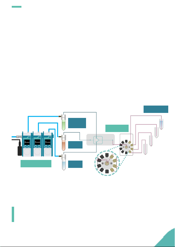
In this application example, up to 10 liquids (4 on the schematic) are
selected sequentially inside the 1-channel chip by the M-SWITCHTM.
The samples at the outlet of the chip are sorted by a 2-SWITCHTM either
into a collector tube or into a waste. Each step can be automated
either by using Microfluidic Automation Tool (MAT) or partially with
live control and monitoring using ESSTM Control dedicated software.
S
This type of set-up suits for applications such as:
• Cell analysis
• Cell lysis and DNA extraction (for PCR or NGS analysis)
• Drug testing
• Calibration curve
M-SWITCHTM
LineUpTM Flow EZ
FLOW UNIT
2-SWITCHTM
Manifold
Reagents
Chip
Recover Waste
Pressure
& power
supply
P-CAP
7
2-SWITCHTM
INTRODUCTION
In this application example, different concentration of the molecule
of interest are injected into the chip thus generating droplets with
different concentrations. These droplets are then sorted at the outlet
of the chip by the M-SWITCHTM depending on their concentrations.
Each step can be automated either by using Microfluidic Automation
Tool (MAT) or partially with live control and monitoring using ESSTM
Control dedicated software.
S
M-SWITCHTM
Molecule
of interest
Water
Oil
Concentration
1
2
3
4
LineUpTM Flow EZ
This type of set-up suits for applications such as:
• Droplet generation
• Concentration dosage
• Sample preparation

8
INTRODUCTION
Several samples are injected simultaneously or separatly within a
Y-shaped chip by changing the position of the three 2-SWITCHTM
placed at the chip inlets. The injected solutions into the chip are
mixed by diffusion and the samples at the outlet are then sorted by
the fourth 2-SWITCHTM. Each step can be automated either by using
Microfluidic Automation Tool (MAT) or partially with live control and
monitoring using ESSTM Control dedicated software.
S
This type of set-up suits for applications such as:
• Chemical mixing reactions
• Stoichiometry study
LineUpTM Flow EZ
FLOW UNIT
2-SWITCHTM
Reagents
Diffusive
mixing chip
Recover Waste
Pressure
& power
supply
P-CAP
2-SWITCHTM

9
2-SWITCHTM
INTRODUCTION
The L-SWITCH™ can be used as a useful cell culture tool: a small
volume of buffer can be recirculated within a closed loop into
the chip for several hours or days. Combined with the LineUpTM
pressure regulation it can achieve a highly stable flow with a
positive impact on the shear stress. The Microfluidic Automation
Tool (MAT) allows to simultaneously and automatically switch
the valve position and the pressurized reservoir so that the flow is
maintained unidirectionally without being stopped.
F
P 1 P 2
This type of set-up suits for applications such as:
• Cell culture
• Shear-stress control
L-SWITCHTM
Buffer Buffer
LineUpTM Flow EZLineUpTM Flow EZ
MATMAT
10
INTRODUCTION
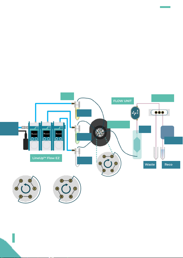
Sample from the reservoir is loaded into a "sample loop" between
two outlets of the L-SWITCHTM while carrier buffer is directly injected
into the chip. When the L-SWITCHTM position is switched the
controlled sample loop volume is injected into the chip along with
carrier buffer. The sample is then sorted by the 2-SWITCHTM at the
outlet of the chip.
C
This type of set-up suits for applications such as:
• Cell culture
• PCR
LineUpTM Flow EZ
FLOW UNIT
RecoverWaste
P-CAP 2-SWITCHTM
Pressure
& power
supply
Waste
Carrier
Sample
L-SWITCHTM
S
Detector
P 1 P 2
Chip
Altri manuali per ESS
1
Indice
Altri manuali Fluigent Unità di controllo

Manuali Unità di controllo popolari di altre marche

Festo
Festo Compact Performance CP-FB6-E Manuale elenco delle parti

Elo TouchSystems
Elo TouchSystems DMS-SA19P-EXTME Manuale utente

JS Automation
JS Automation MPC3034A Manuale utente

JAUDT
JAUDT SW GII 6406 Series Guida rapida

Spektrum
Spektrum Air Module System Manuale utente

BOC Edwards
BOC Edwards Q Series Manuale utente


