ForceDoor BASE 35 Manuale di istruzioni

Industrial Door Drive
Control System
Instructions And User Guide
Version 1.8
BASE 35

CONTENTS
1. GENERAL SAFETY INFORMATION .................................1
2. TECHNICAL DATA ................................................ 2
3. OVERVIEW OF CONTROL .........................................3
4. BASIC BUTTON INSTRUCTION ................................... 4
5. COMMON FUNCTION QUICK SETTING INSTRUCTION .............. 5
6. QUICK SETTING TO GUIDE THE DRIVE WORKS BY "AAS" ........ 6-7
7. FUNCTION TABLE MENU ITEMS ...................................8
8. FUNCTION MENU DESCRIPTION ...............................9-29
9. FAULTS ..................................................... 30-31
10. TX/RX FUNCTION MODULE DESCRIPTION ................... 32-33
11. FUNCTION WIRING DIAGRAM ............................... 33-40

1
GENERAL SAFETY INFORMATION
Specified use
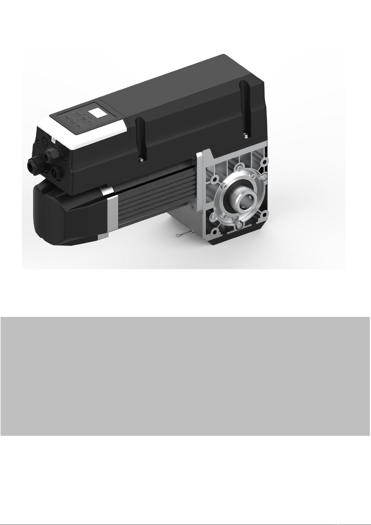
The industrial door drives intended for a power-operated door with a drive unit.
The safe operation is only guaranteed with specified normal use. The drive unit
is to be protected from rain, moisture and aggressive ambient conditions. No
liability for damage caused by other applications or non-observance of the
information in the manual.
Modifications are only permitted with the agreement of the manufacturer.
Otherwise the Manufacturer’s Declaration shall be rendered null and void.
Safety information
Installation and commissioning are to be performed by skilled personnel only.
Only trained electrical craftsmen are permitted to work on electrical equipment.
They must assess the tasks assigned to them, recognize potential danger zones
and be able to take appropriate safety measures.
Installation work is only to be carried out with the supply off.
Observe the applicable regulations and standards.
WARNING: Important safety instructions.
- It is vital for the safety of people to follow all instructions. Keep this manual.
- Do not let children play with the appliance or control devices including remote
controls.
- Follow all instructions, as incorrect installation can lead to serious injuries.
- The actuating element of the dependent switch must be positioned so that it
can be seen directly on the driven part, but out of reach of the moving parts. If
it is not actuated by a key, it must be placed at a minimum height of 1.5 m and
not accessible to the public;
after installation, make sure that the mechanism is set correctly and that the
protection system and any manual controls work properly.
Coverings and protective devices
Only operate with corresponding coverings and protective devices.
Ensure that gaskets are fitted correctly and that cable glands are correctly
tightened.
Weighted sound pressure emission level A of the motor
LpA less than or equal to 70 dB (A).
WARNING Z101 . - The effect of noise emitted by the structure, including the
driven part to which the drive will be connected, is not considered.
Spare parts
Only use original spare parts.

2
TECHNICAL DATA
Model
BASE 35
Max. output torque(Nm)
35 Nm
Rated output torque(Nm)
25 Nm
Output speed(rpm)
24-32 rpm
Output shaft/hollow shaft(mm)
φ25.4 mm
Static holding torque(Nm)
400 Nm
Door area(m²)
≤18 m²
Input voltage(V)
110-127V/220-240V
Motor power(W)
350 W
Control system
24V DC
Thermal protection temperature(°C)
105 °C
Max. cycles per hour(Cycle)
20 cycles
Class of protection
IP 54
Limit switch range
(maximum revolutions of output shaft /
hollow shaft)
15 turns
Temperature range(°C)
-20°C~+40°C

3
OVERVIEW OF CONTROL
Digital display:
The first boot up displays ,then
count down from to .
: Without travel limit set.
: With travel limit set.
Button : UP/STOP
Button : STOP
Button: DOWN/STOP

4
BASIC BUTTON INSTRUCTION
Item
Button
Description
1.
Short press: Confirm setting;
Long press: Enter the function menu setting
2.
Short press: Adjust the function menu
Long press: Restore factory setting
3.
Short press: Adjust the function menu
Long press: Running cycle counter inquiry
4.
Short press: Return
Long Press: Enter into rail system selection
(Refer to the quick operation guide for details - Page 6)
5.
Short press: Quick activate “AUTO CLOSE” function
6.
Short press: Quick activate “FORCE MARGIN” function

5
COMMON FUNCTION QUICK SETTING INSTRUCTION
Function
Item
Operation
Description
AUTO CLOSE
Short press:
Important:
The “AUTO CLOSE” only can be activated when the Photo
beam or light curtain has been correctly installed and the
photo beam function has been enabled from function menu
(Refer to page 18 - Menu 5).
Short press the “AUTO CLOSE”button, when the
indicator light is turned on. It means the “AUTO
CLOSE”function has been activated.
(Default: The door only can auto close while in the open
limit position. And the Auto Close time is 15 seconds).
Note: Refer to page 16 - Menu 4 to change any setting
for AUTO CLOSE conditions or time if necessary.
Note: If there is no any photo beam or light curtain
installed, the door can not be closed, and the LED display
will show the letter “E6” as an indication.
Short press the “AUTO CLOSE”button, when the
indicator light is turned off. It means the “AUTO
CLOSE”function has been dis-activated.
Force
Adjustment
Short press:
Short press the button, the digital display will indicate
the current force level firstly
Continually short press the button: Incremental rolling
display the force level between to
L1: Minimum force level ;
L9: Maximum force level
Note: L3 to L7 is recommended.
Running
Cycle
Counter
Inquiry
Long press
the button for 6 seconds:
The digital will rolling display
, it represents the drive has
been 10 running cycles worked.
Note: The running cycles is displayed in 6 digits
Restore
Factory
Setting
Long press
the button for 10 seconds:
The digital will rolling display
,then release the button, it means the
drive has been restored to factory setting.
Note: The running cycle counter record will not been
cleared.

6
Important:
"AAS" will automatic identify the door condition to define a best program
for its "Open/ Close speed", "Soft start/ soft stop ranges" and "Force sensitivity".
A quick setting guide the drive will work properly after below operation.
QUICK SETTING TO GUIDE THE DRIVE WORKS
BY "AAS" (Auto adaptive system)
1.Long press:
over 3 seconds to
enter into RAIL
SYSTEM
selection
All of the indicator lights are light up constantly for “SL,HL,VL”and then off.
Then release the button until one of the indicator lights flashes.
2.Short press:
/
to select the
corresponded
RAIL SYSTEM of
the door.
The corresponded light flashes for “SL,HL,VL”
SL: Standard lift sectional doors with cylindrical cable drum
HL:High lift sectional doors with cylindrical-conical cable drum
VL:Vertical lift sectional doors with conical cable drum
3.Short press:
to confirm the
selected Rail
System
The corresponded indicator light is constant on for “SL,HL,VL”
Then, the digital display shows to start the OPEN travel limit setting.

7
4. Long press:
/
Long press the button UP/DOWN to set the door to the target OPEN limit position,
then release the buttons.
Short Press the SET button once to store the open limit position, the digital displays
to start the CLOSE travel limit setting.
5. Long press:
/
Long press the button UP/DOWN to set the door to the target CLOSE limit position
then release the buttons.
Short press the SET button once to store the CLOSE limit position, then the door
drive will automatically open and close the door to store the door weight and
spring balance conditions.
Note:
a. If a system selection error occurs during the setting process, please
click ,Execute enter to exit the setting, and then execute the first
operation again.
b. Active or change any stand alone function, refer to the below
"FUNCTION TABLE MENU".

8
FUNCTION TABLE MENU ITEMS
MENU
Function Table Menu
Status Indications
0
Travel Limit Setting
1
Common Function Setting
2
Operating Parameter Setting
3
Soft Stop (during-operation) Function Setting
4
AUTO CLOSE Time & Condition Setting
5
Infrared Beam & Light Curtain Function
6
Terminals for Extra Function Setting
7
Courtesy Light Function Setting
8
Maintenance Alarm Function Setting
9
Gear Motor Running Direction Rotating Setting
Indice
Altri manuali ForceDoor Azionamento CC
Manuali Azionamento CC popolari di altre marche

Vincent Associates
Vincent Associates UNIBLITZ ED12DSS Manuale utente

EKSMA OPTICS
EKSMA OPTICS DQ-100-4 Manuale elenco delle parti

Chamberlain Garog
Chamberlain Garog D Series Manuale utente

Parker
Parker PDS Series Manuale utente

Festo
Festo DGC G Series Guida all'installazione

Binks
Binks QS-5012-1-CE Manuale utente


