
Grundig GSS HADA 5100 SPTS Manuale utente

Assembly Instruction
HADA 5100 SPTS

- 2 - HADA 5100 SPTS
Contents
1 Safety regulations and notes ..............................................................................3
2 General information ..........................................................................................4
2.1 Packing contents ................................................................................ 4
2.2 Meaning of the symbols used ............................................................... 4
2.3 Technical data.................................................................................... 4
2.4 Description ........................................................................................ 5
2.5 Software query .................................................................................. 6
3 Assembly ..........................................................................................................7
3.1 Installing the cassette .......................................................................... 7
3.2 EMC regulations ................................................................................ 8
3.3 Cassette overview .............................................................................. 9
3.4 Connecting the cassette ....................................................................... 9
4 The control panel at a glance ...........................................................................10
4.1 Menu items ...................................................................................... 10
4.2 Control panel ................................................................................... 10
5 Programming ..................................................................................................11
5.1
Programming procedure .........................................................................11
5.2 Programming the cassette .................................................................. 13
Selecting the cassette ................................................................... 13
Ethernet parameters..................................................................... 14
Hardware IP address ................................................................... 14
Address range ............................................................................ 15
Address of the gateway ............................................................... 15
UDP port .................................................................................... 16
Input .......................................................................................... 16
Output IP addresse ...................................................................... 17
Switching the IP address off or on ................................................. 17
Transmission protocol .................................................................. 17
Port number ................................................................................ 17
Quantity of data packets .............................................................. 18
Forward error correction .............................................................. 18
Transmission channel ................................................................... 18
Stuffing the output data rate ......................................................... 20
Displaying the output data rate ..................................................... 20
Factory reset............................................................................... 21
Saving settings ............................................................................ 21
6 Final procedures ..............................................................................................22
- 3 - HADA 5100 SPTS
1 safety regulations and notes
• Assembly, installation and servicing should be carried out by authorised
electricians.
• Switch off the operating voltage of the system before beginning with assem-
bly or service work or pull out the mains plug.
• Do not perform installation and service work during thunderstorms.
• Install the system so it will not be able to vibrate…
- in a dust-free, dry environment
- in such a manner that it is protected from moisture, fumes, splashing water
and dampness
- somewhere protected from direct sunlight
- not within the immediate vicinity of heat sources
- in an ambient temperature of 0 °C to +50 °C. In case of the formation of
condensation wait until the system is completely dried.
• Ensure that the head-end station is adequately ventilated. Do not cover the
ventilation slots.
• Beware of short circuits
• No liability is accepted for any damage caused by faulty connections or
inappropriate handling.
• Observe the relevant standards, regulations and guidelines on the installa-
tion and operation of antenna systems.
• The standards IEC/EN/DIN EN 50083 resp. IEC/EN/DIN EN 60728 must
be observed.
• For further information please read the assembly instructions for the head-
end station used.
• Test the software versions of the head-end station and the cassette and
update them if necessary. The current software versions can be found at
"www.mygss.eu".
Take action to prevent static discharge when working on the device!
Electronic devices should never be disposed of in the household rubbish. In ac-
cordance with directive 2002/96/EC of the European Parliament and the
European Council from January 27, 2003 which addresses old electronic
and electrical devices, such devices must be disposed of at a designated
collection facility. At the end of its service life, please take your device to
one of these public collection facilities for proper disposal.
- 4 - HADA 5100 SPTS
2 general information
2.1 PaCking Contents
1 Cassette HADA 5100 SPTS 1 LAN cable
5 BNC cable 1 Brief assembly instructions
2.2 meaning of the symbols used
Important note
—> General note
• Performing works
2.3 teChniCal data
The devices meet the following EU directives:
2011/65/EU, 2014/30/EU, 2014/35/EU
The product fulfils the guidelines and standards for CE labelling (page 23).
Unless otherwise noted all values are specified as "typical".
LAN interface
Standard: ............................................................ 10-BASE-T, IEEE 802.3i
100-BASE-TX, IEEE 802.3u
1000-BASE-X , IEEE 802.3z
Data rate: ............................................................................. ≤ 180 MBit
Protocols: .......................................................... UDP (User Data Protocol),
RTP (Real-Time Transport Protocol)
ASI interfaces
Standard: .....................................................................DIN EN 50083-9
Format: ..............................................................MPEG ISO IEC 13818-1
User data rate: .................................................................2 … 90 Mbit/s
Impedance: .................................................................................... 75 Ω
Max. data rate: .....................................................................180 MBit/s
Level: ........................................................................... 800 mVPP ± 10%
Return loss (input):...............................................> 17 dB (5 … 270 MHz)
- 5 - HADA 5100 SPTS
Connections
LAN: ................................................................................ 1 RJ 45 socket
ASI inputs: .............................................................. 5 BNC sockets, 75 Ω
Connection strip (10-pin): ..................for supply voltages and control circuits
RS 232 socket: ..................................... serial interface for software update
2.4 desCriPtion
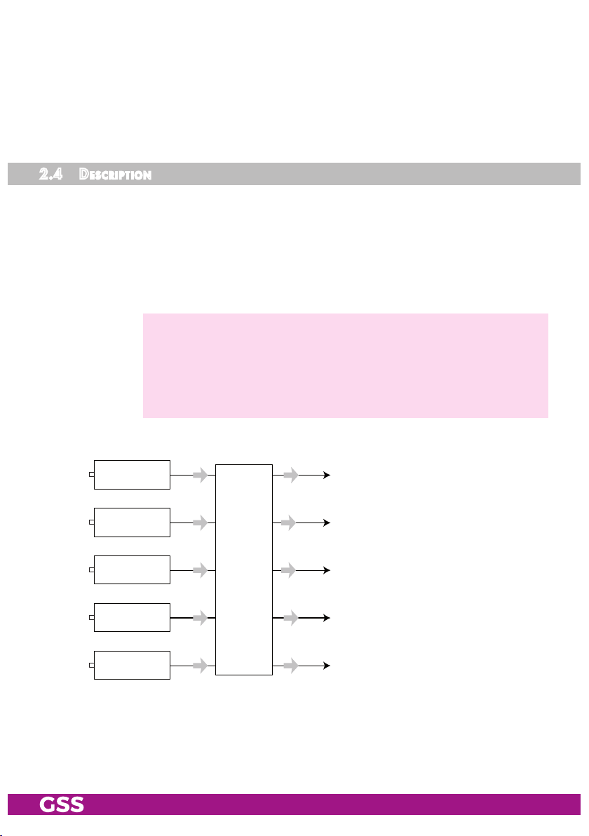
The cassette converts five ASI input channels (ASI – Asynchronous Serial Inter-
face according to DIN EN 50083-9) into five IPTV output channels.
The fed in transport streams will be emitted unchanged at the LAN interface as
SPTS/MPTS transport streams (five output IP addresses).
For operating the cassette in a LAN network it can be assigned its own hardware
IP address.
—> Two IP address ranges are used:
"Hardware" IP addresses (menu ETHERNET), which are used to
connect the cassettes in the network (e.g. 192.168.0.x).
"IPTV" IP addresses (menu IP-OUT), which are used to send the IPTV
channels (multicast range e.g. 227.40.50.x).
Principle signal path:
IP Transportstream 1 ; 227.40.50.1
IP Transportstream 2 ; 227.40.50.2
IP Transportstream 3 ; 227.40.50.3
IP Transportstream 4 ; 227.40.50.4
IP Transportstream 5 ; 227.40.50.5
ASI input 5
ASI input 4
ASI input 3
ASI input 2
ASI input 1
TPS
- 6 - HADA 5100 SPTS
The cassette is controlled with the head-end station control unit.
The LEDs for the LAN interface show whether a network connection exists and
whether a data transfer is in progress.
When the head-end station is switched on, the two-line LC display shows the
software version of the control unit.
To operate this cassette the software version of the control unit must be "V 45"
or higher. You can find the current operating software for the control unit and
the cassette, the software "BE-Flash" and the current assembly instructions on
the website "www.mygss.eu".
The cassette is intended for use in the
STANDARD LINE
head-end stations.
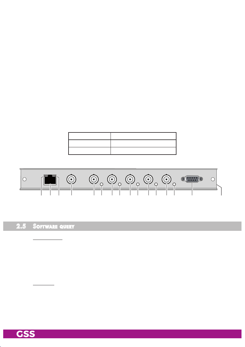
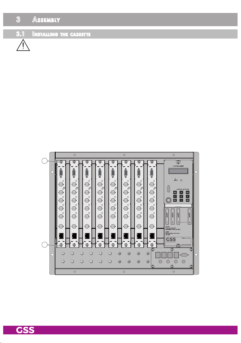
Five LEDs (6, 8, 0, @, $) indicate by their colour whether an input
signal is present:
LED colour Indication
Green Signal present
Red no Signal
1 2 3 $ % ^@ #9 0 !7 85 64
2.5 soft ware query
Control unit
If necessary, you can activate the indication of the software version of the
control unit manually:
• Press any two keys on the control unit of the head-end station simultaneously
until the display goes dark and the software version, e.g. "V 45" appears.
Cassette
After activating the cassette the software version of the cassette is displayed
(see page 13).
- 7 - HADA 5100 SPTS
3 assembly
3.1 installing the Cassette
– Ensure the head-end station is mounted so it will not be able to vibrate.
Avoid, for example, mounting the head-end station onto a lift shaft or any
other wall or floor construction that vibrates in a similar way.
– Before installing or changing a cassette unplug the power cable from the
mains power socket.
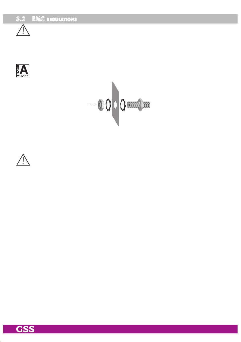
• Remove the fastening screws 1 of an unoccupied slot from the bracket of
the head-end station.
• Insert the cassette in this slot and push it into the housing.
• Align the cassette and apply slight pressure to connect it to the connections
of the board and the RF bus bar.
• Fasten the cassette with the screws 1.
1
1
- 8 - HADA 5100 SPTS
3.2 emC regulations
To comply with the current EMC regulations, it is necessary to connect the lines
leading in and out of the head-end station using cable terminals.
When mounting the cassette in a head-end station which is installed in a 19"
cabinet, make sure the connections leading in and out for the 19" cabinet are
made using cable terminals.
CLASS
KLASSE
The attenuation of shielding of the connection lines for ASI and antenna must
meet the requirements for "Class A".
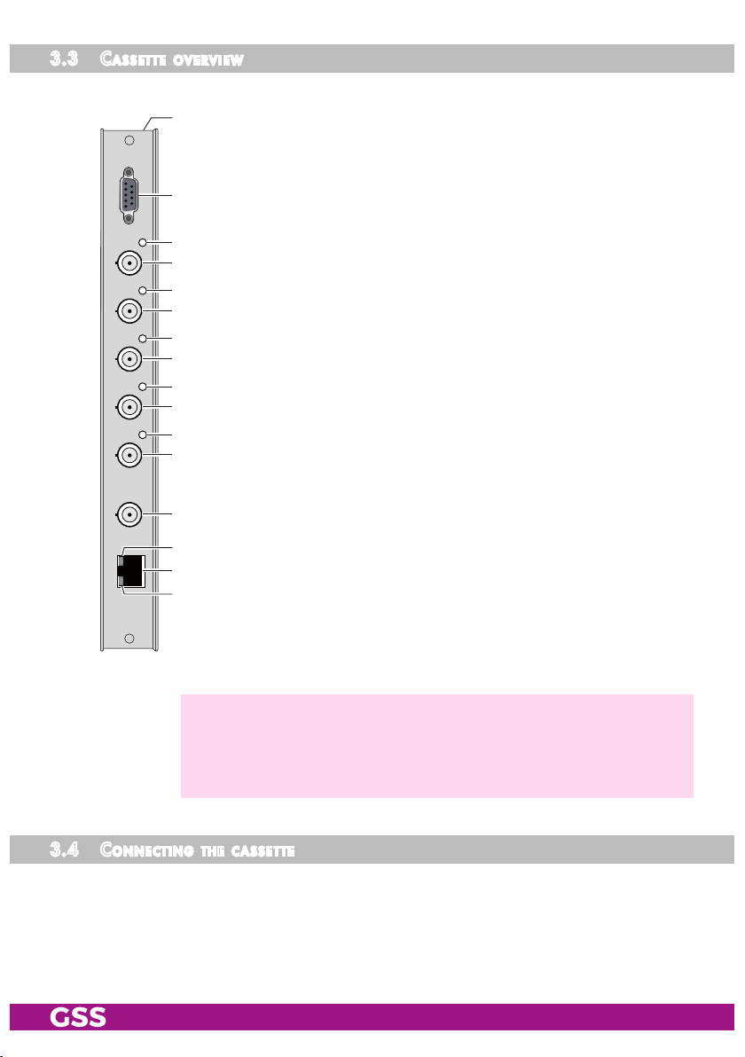
• Insert the required number of cable terminals in the openings provided in
the head-end station or in the 19
"
cabinet.
Tighten the nuts on the cable terminals until the teeth on the lock washer have
penetrated the exterior coating and a good connection is made between the hous-
ing and cable terminals.
- 9 - HADA 5100 SPTS
3.3 Cassette overview
1
2
3
$
%
^
@
#
9
0
!
7
8
5
6
4
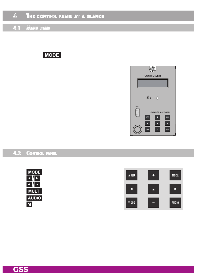
1 Status LED of the LAN interface (data transfer)
2
LAN socket
3
Status LED of the LAN interface (network connection)
4
without function
5 ASI input 5
6 Status LED ASI input 5
7 ASI input 4
8 Status LED ASI input 4
9 ASI input 3
0 Status LED ASI input 3
! ASI input 2
@ Status LED ASI input 2
# ASI input 1
$ Status LED ASI input 1
% D-SUB socket "RS 232"
^ Type label + MAC address (at the frame)
—> The operating software of the cassette can be updated via the 9-pin
D-SUB socket "RS 232" using a PC or notebook and the software
"BE-Flash". You can find the current operating software on the web-
site "www.mygss.eu".
3.4 ConneCting the Cassette
• Connect the LAN socket
2
.
• Connect the ASI inputs
5
,
7
,
9
,
!
,
#
to the peripheral ASI devices.
- 10 - HADA 5100 SPTS
4 the Control Panel at a glanCe
4.1 menu items
Programme the
cassette
using the buttons on the control unit of the head-end
station. The two-line display of the control unit then shows the menus.
The parameters and functions to be set are underlined.
Use the key to select the following main menu items:
– Ethernet parameter
– Output parameter
– Datamode
– Displaying the data rate
– Factory reset
4.2 Control Panel
The key pad on the head-end station is used to scroll through the menus:
scrolls forward through the menus.
select parameters in the menus.
set values, initiate actions.
selects sub-menus.
scrolls backward through the menus.
saves all entries.
BE-Remote V 45
please wait . . .
Indice
Altri manuali Grundig Unità di controllo


Manuali Unità di controllo popolari di altre marche

Festo
Festo Compact Performance CP-FB6-E Manuale elenco delle parti

Elo TouchSystems
Elo TouchSystems DMS-SA19P-EXTME Manuale utente

JS Automation
JS Automation MPC3034A Manuale utente

JAUDT
JAUDT SW GII 6406 Series Guida rapida

Spektrum
Spektrum Air Module System Manuale utente

BOC Edwards
BOC Edwards Q Series Manuale utente


