HAWE Hydraulik CDK Series Manuale dell'operatore

Pressure-reducing valve type CDK
Product documentation
D 7745
09-2019-1.9
Screw-in valve
Operating pressure pmax:
Volumetric ow rate Qmax:
500 bar
22 l/min

2/25 D 7745 - 09-2019-1.9 © HAWE Hydraulik SE
© by HAWE Hydraulik SE.
The reproduction and distribution of this document as well as the use and communication of its contents to others without explicit
authorisation is prohibited.
Offenders will be held liable for the payment of damages.
All rights reserved in the event of patent or utility model applications.
Brand names, product names and trademarks are not specifically indicated. In particular with regard to registered and protected names
and trademarks, usage is subject to legal provisions.
HAWE Hydraulik respects these legal provisions in all cases.
Printing date / document generated on: 11.11.2019

© HAWE Hydraulik SE D 7745 - 09-2019-1.9 3/25
Contents
1 Overview pressure control valve type CDK............................................................................................................ 4
2 Available versions, main data............................................................................................................................. 5
2.1 Screw-in valve..................................................................................................................................................... 5
2.2 Versions with individual connection block for pipeline connection..............................................................................6
2.3 Versions with individual connection block for plate mounting....................................................................................7
3 Parameters......................................................................................................................................................... 8
3.1 General............................................................................................................................................................... 8
4 Dimensions...................................................................................................................................................... 12
4.1 Screw-in valve................................................................................................................................................... 12
4.2 Mounting hole................................................................................................................................................... 13
4.3 Version with single connection block for pipe connection........................................................................................14
4.4 Version with connection block for manifold mounting............................................................................................. 17
4.5 Base plate hole pattern...................................................................................................................................... 18
4.6 Tapped plugs..................................................................................................................................................... 18
5 Assembly, operation and maintenance recommendations.....................................................................................19
5.1 Intended use..................................................................................................................................................... 19
5.2 Assembly information......................................................................................................................................... 19
5.2.1 Screwing in the screw-in valve.............................................................................................................................20
5.2.2 Setting the pressure........................................................................................................................................... 20
5.2.3 Creating the mounting hole.................................................................................................................................21
5.2.4 Making base plate.............................................................................................................................................. 21
5.3 Operating instructions.........................................................................................................................................22
5.4 Maintenance information..................................................................................................................................... 22
6 Other information.............................................................................................................................................23
6.1 Planning information.......................................................................................................................................... 23
6.2 Application examples.......................................................................................................................................... 24

4/25 D 7745 - 09-2019-1.9 © HAWE Hydraulik SE
1Overview pressure control valve type CDK
Pressure reducing valves are a type of pressure control valve. They
maintain a largely constant outlet pressure even at a variable
(higher) inlet pressure.
Valve type CDK is a screw-in valve, and can be used in control
blocks. The bore-holes required for mounting are easy to create. All
versions oil-tight when closed.
Features and benets:
■Zero leakage in closed state
Intended applications:
■General hydraulic systems
■Jigs
■Test benches
Design:
■Type CDK 3 - standard version, can be used for all applications.
■Type CDK 32 - version with low pressure dependence on
changing pump inlet pressure and for usage at low pressure
settings.
■Type CDK 35 - version with low ow resistance, however with
higher pressure dependence on changing pump inlet pressures.
Version with connection blocks:
■For pipe connection (without/with pressure-limiting valve)
■For manifold mounting (without/with pressure-limiting valve)
■For manifold mounting (without/with pressure-limiting valve)
with adapter plate for pipe connection
Screw-in valve
Version with connection block for direct pipe connection
Version with connection block for manifold mounting

© HAWE Hydraulik SE D 7745 - 09-2019-1.9 5/25
2Available versions, main data
2.1 Screw-in valve
Circuit symbol:
NOTE
Flow direction A d P not shown, see "Flow direction" section in Chapter 3.1, "General"
Sample order:
CDK 3 -2 R -200
Pressure setting (bar) Pressure control valve *
Adjustment Table 2 Adjustment
Basic type and pressure range Table 1 Basic type and pressure range
* If there is no specied pressure setting, the valve will be set at the factory to the maximum value in the pressure range in question
Table 1 Basic type and pressure range
Pressure range pA from ... to (bar)Type Volumetric
ow rate
Qmax (lpm) -08 -081 -1 -11 -2 -21 -5 -51
CDK 3 50 ... 450 50 ... 500 30 ... 300 30 ... 380 20 ... 200 20 ... 250 15 ... 130 15 ... 165
CDK 3K*12 55 ... 310 - 30 ... 200 - 20 ... 140 - 15 ... 90 -
CDK 32 6 30 ... 450 30 ... 500 18 ... 300 18 ... 380 12 ... 200 12 ... 250 8 ... 130 8 ... 165
CDK 32K*6 30 ... 310 - 18 ... 200 - 12 ... 140 - 8 ... 90 -
CDK 35 22 110 ... 450 110 ... 500 70 ... 300 70 ... 380 50 ... 200 50 ... 250 30 ... 130 30 ... 165
CDK 35K*22 110 ... 310 - 70 ... 200 - 50 ... 140 - 30 ... 90 -
*Short version, available "xed" only
Table 2 Adjustment
Identifier Description Circuit symbol
No designation Fixed, can be adjusted using tool
RCan be adjusted by hand, with lock nut
(not for type CDK 3.K)
HRotating grip with lock
(not for type CDK 3.K)

6/25 D 7745 - 09-2019-1.9 © HAWE Hydraulik SE
2.2 Versions with individual connection block for pipeline connection
Sample order:
CDK 3 -5 R
CDK 35 -2
-1/4
-1/4 SR
- DG 365 -100
-200 /250
Pressure setting (bar) Pressure relief valve
Version with pressure switch Table 4 Version with pressure switch
Versions with individual connection block Table 3 Versions with individual connection block
Table 3 Versions with individual connection block
Identifier Description Connection Circuit symbol
-1/4 G 1/4 (BSPP)
-9/16-18 UNF 9/16-18 UNF
-1/4-18 NPTF 1/4-18 NPTF
-1/2
Pipe connection
G 1/2 (BSPP)
-1/4 - DG.. G 1/4 (BSPP)
-9/16-18 UNF - DG.. 9/16-18 UNF
-1/4-18 NPTF - DG..
Pipe connection, pressure switch in the load line
1/4-18 NPTF
-1/4 S Pipe connection, pressure-limiting valve, xed, tool adjustable G 1/4 (BSPP)
-1/4 SR Pipe connection, pressure-limiting valve, manually adjustable, with
lock nut
G 1/4 (BSPP)
NOTE
Connection M with reduced ow.
Table 4 Versions with pressure switch
Coding Setting range (bar)
- DG 33 200 ... 700
- DG 34 100 ... 400
- DG 35 40 ... 210
- DG 36 4 ... 12
- DG 364 4 ... 50
- DG 365 12 ... 170

© HAWE Hydraulik SE D 7745 - 09-2019-1.9 7/25
2.3 Versions with individual connection block for plate mounting
Sample order:
CDK 35 -5 R - SP -100/300 - 1/4
Adapter plate Table 5 Connection block version
Connection block Table 5 Connection block version
Table 5 Connection block version
Identifier Description Circuit symbol
PPlate mounting
SP Plate mounting, pressure relief valve, xed, can be adjusted using tool
P - ... - 1/4 Plate mounting
SP - ... /... - 1/4 Plate mounting, pressure relief valve, xed, can be adjusted using tool, with adapter plate
for pipeline connection

8/25 D 7745 - 09-2019-1.9 © HAWE Hydraulik SE
3Parameters
3.1 General
General information
Designation Directly piloted 2-way pressure control valve
Design Ball seated valve
Model Screw-in valve, valve for pipe connection, manifold mounting valve
Material Steel; nitrided valve housing, electrogalvanised or ZiNi sealing nuts and connection block,
hardened and ground functional inner parts
Balls made of rolling bearing steel
Tightening torque See Chapter 4, "Dimensions"
Installation position As desired
Ports ■P = input (pump side or primary side)
■A = Load (secondary side)
■M = pressure gauge connection
■R = Tank connection
Markings apply to hydraulic schematics and assembly plans only. The markings are not
stamped onto the valve housing.
The ports are stamped on the versions for pipe connection and versions for manifold
mounting.
The coding can be found in the schematic overviews or the dimension diagrams in Chapter 4,
"Dimensions".
Flow direction P → A: Pressure control function
A → P: Only possible if the pressure on the pump side is lower than the load pressure.
NOTE
In the case of ow rates of A d P with more than QP d A max or if pressure surges
or pressure pulsations are to be expected, a separate bypass check valve is to be
provided.
Hydraulic uid Hydraulic oil: according to part 1 to 3;
ISO VG 10 to 68 according to DIN ISO 3448
Viscosity limits: min. approx. 4, max. approx. 1500 mm2/s
opt. operation approx. 10... 500 mm2/s.
Also suitable for biologically degradable hydraulic uids type HEPG (polyalkylene glycol)
and HEES (synthetic ester) at operating temperatures up to approx. +70°C.
Cleanliness level ISO 4406
21/18/15...19/17/13
Temperatures Ambient: approx. -40 ... +80°C, Fluid: -25 ... +80°C, Note the viscosity range!
Permissible temperature during start: -40°C (observe start-viscosity!), as long as the service
temperature is at least 20K higher for the following operation.
Biologically degradable pressure uids: Observe manufacturer's specifications. By considera-
tion of the compatibility with seal material not over +70°C.

© HAWE Hydraulik SE D 7745 - 09-2019-1.9 9/25
Pressure and ow rate
Operating pressure ■On the pump side pP max = 500 bar
■Load side pA max, see Table for basic version in Chapter 2, "Available versions, main data"
■Return pR ≤ 20 bar
Pressure dependence The pressure ratio as designed causes a slight change to the actual pressure pA in conjunction
with a variable pump pressure pP.
Pressure range (bar)Type
-08
-081
-1
-11
-2
-21
-5
-51
CDK 3 ± 1.3 ± 0.9 ± 0.6 ±0.4
CDK 32 ± 0.7 ± 0.45 ± 0.3 ± 0.23
CDK 35 ± 2.7 ± 1.7 ± 1.2 ± 0.8
pp ± 10 bar results in a pressure change for A of pA
Flow rate QP→A max = 6 lpm (CDK 32)
= 12 lpm (CDK 3)
= 22 lpm (CDK 35)
QA→P max = 25 lpm See note in Chapter 3, "Parameters"
10/25 D 7745 - 09-2019-1.9 © HAWE Hydraulik SE
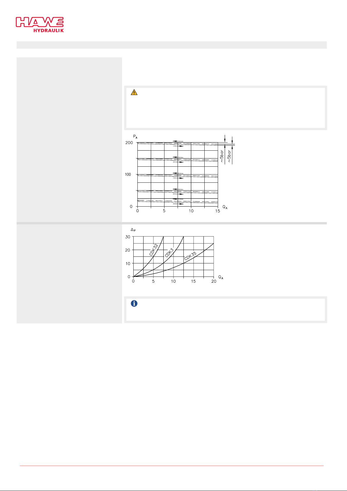
Characteristics
Oil viscosity approx. 60 mm2/s
pA - QP→A - characteristics
The pressure setting applies for QP→A→0 lpm. If Q > 0, i.e. the connected consumer is
moving, the secondary pressure pA drops slightly.
The pressure pA is set according to the information in the order at pP ≈ 1.1 pA.
CAUTION
Risk of injury on overloading components due to incorrect pressure settings!
Risk of minor injury.
■Pay attention to the maximum operating pressure of the pump and the valves.
■Always monitor the pressure gauge when setting and changing the pressure.
QA ow rate (lpm); pA outlet pressure (bar)
Δp - Q - Characteristic curve P→A or A→P
QA Volumetric ow rate (lpm); Δp Flow resistance (bar)
NOTE
For this purpose, please observe the additional information under the point "Flow
direction".
Questo manuale è adatto per i seguenti modelli
3
Indice
Altri manuali HAWE Hydraulik Unità di controllo

Manuali Unità di controllo popolari di altre marche

Festo
Festo Compact Performance CP-FB6-E Manuale elenco delle parti

Elo TouchSystems
Elo TouchSystems DMS-SA19P-EXTME Manuale utente

JS Automation
JS Automation MPC3034A Manuale utente

JAUDT
JAUDT SW GII 6406 Series Guida rapida

Spektrum
Spektrum Air Module System Manuale utente

BOC Edwards
BOC Edwards Q Series Manuale utente


