Inelco Dania SSH Manuale utente

08- 2023 JD
System stationary heater
Stacjonarna nagrzewnica elektryczna
Dania SSH 5kW– 22kW
Instruction manual / Instrukcja obsługi
PL
EN

2
EN
Electric System Stationary Heater
Dania SSH 5-22kW
Important: read the entire user manual before device us-
ing, repair or cleaning. Improper use may cause injuries,
burns, electric shock or re. The appliance is not intended
for use by persons (including children) with reduced physical, sen-
sory or mental capabilities, or lack of experience and knowledge,
unless they have been given supervision or instruction concerning
use of the appliance by a person responsible for their safety. Chil-
dren should be supervised to ensure that they do not play with the
appliance.
Keep these instructions in a safe place for future reference.
SAFETY WARNINGS!
Do not cover – danger of re!
The appliance has hot surfaces during operation!
Ensure that the area around the intake and the exhaust grille
is kept free from material which could obstruct or stop the air
ow through the appliance.
Do not place the heater where inammable materials may be
placed on or near the heater!
The appliance must not be covered either with clothes or sim-
ilar material since overheating of the appliance can result in a
re hazard.
Do not use this heater in the immediate surroundings of a
bath, a shower or a swimming pool!
Do not cover the heater, the heater must not be exposed to
excess dust and humidity!
Do not use the heater outdoors !
Do not place the heater immediately below a socket-outlet!
Use this heater xed to the wall by dedicated wall bracket.
Do not use this heater if it has been dropped!
Do not use if there are visible signs of damage to the heater!
The space heater must only be disassembled by the manufac-
turer or a qualied service engineer!
The power cable must only be connected or replaced by the
qualied specialist!

3
Figure 1. Unit elements description.
1. Control LED
2. Heating element
3. Wallmount xing screw
4. Power cable gland
5. Control cable entry dummy plug
6. Fan with electric motor
7. Wallmount bracket
8. Vertical air ow direction adjustment
4
Purpose
The DANIA SSH electric stationary heaters are not intended for use
other than indoors. These heaters are suitable for the heating of ware-
houses, production halls, workshops, storage rooms, show rooms, gar-
ages etc.
Operation
The air is carried through the heater by a fan (gure 1 pos.6) and heat-
ed by heating elements (gure 1 pos.2) which are regulated by the ex-
ternal thermostat unit and Control Box . The air speed is non-
adjustable. There are two fan works regime available: fan works only
when thermostat is ON or fan works all the time -even when thermo-
stat is OFF. For details please refer to gure 5 or gure 6 appropriately .
Inelco recommend Salus 091FLV2 thermostat with programmer to be
used with DANIA SSH stationary heaters. For more details please refer
to gure 9.
IMPORTANT: the heater must be connected to the control
box and an external thermostat/regulator. One control box
and one thermostat/regulator can control one heater or a
set of up to 6 heaters.
Switching on or off, selecting half or full output power or fan mode is
performed through the Control Box, which is wall mounted for easy
access. For details please refer to gure 10. Heaters is protected from
overheating via a built-in temperature limiter. To reset, see Overheat-
ing (page 12). Heater is mounted on a wall with a wallmount bracket,
which allows to obtain 3 various vertical and 3 various horizontal posi-
tions—please see gure 3 and gure 4.
Mechanical installation
The DANIA SSH kW stationary heater is intended for wall mounting.
The appliance must not be placed directly under a wall-outlet. The
minimum distances given in gure 2 must be kept. The heaters must
not be mounted on the ceiling.
1. Mark holes by means of the wallmount bracket.
2. Drill holes for the xing wall plugs.
3. Mount the bracket.
4. Mount the fan heater on the bracket and adjust the heater to

5
desired vertical and horizontal position (refer to gures 3 and 4).
5. Screw the bottom bolt in and tighten all bolts.
Use wall fasteners appropriate for the wall material and weight of the
unit with a reasonable safety margin.
Figure 2. Mounting on wall. Minimum distances.
In order to ensure to the heater proper working conditions, the mini-
mum distances from the ceiling, walls located on the sides of the
heater and the minimum installation place height should be main-
tained.
The correct location of the heater installation will ensure effective
and uniform heating of the room, safety of use and will protect peo-
ple passing by from the possibility of collision with the heater.
The recommended minimum distances are:
1. 0.3m from the ceiling
2. 1.0 m from the side walls
3. The minimum installation height from the oor is 1.8 m or higher
depending on the processes taking place near the heater.

6
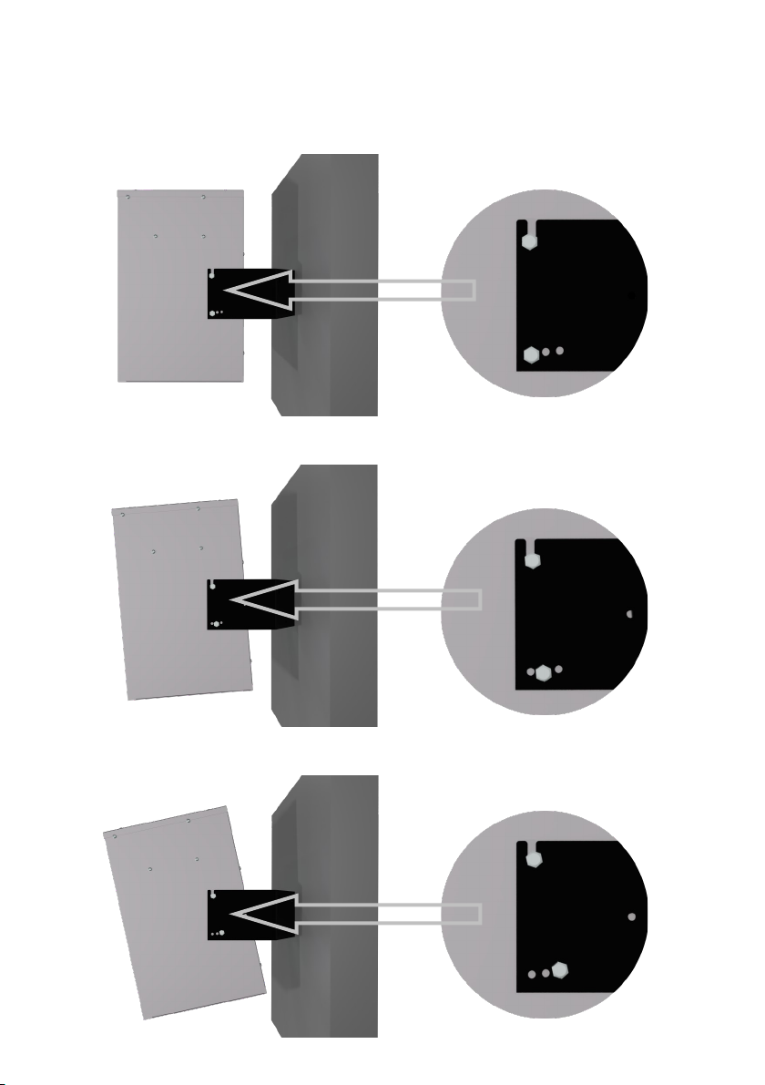
Figure 3. Mounting on the wall. Horizontal positions.
Pos.1 Pos.2
Pos.3
The wall bracket allows to obtain 3
various horizontal positions in rela-
tion to the mounting plane (wall):
pos.1 perpendicular to the wall
pos.2 tilted to the left
pos.3 tilted to the right
There are 3 positions of the heated air ow adjustment in the vertical
plane available:
1. horizontal airow (gure 4 pos. a)
2. slightly downward airow (Figure 4 pos. b)
3. slightly downward airow (Figure 4 pos. c).
To get right direction please choose one of mounting position available
in the wallmount bracket. For details please see gure 4.
7
Figure 4. Mounting on the wall. Vertical positions
A. Vertical position
B. Slightly downward direction
C. Max downward direction

8
Electrical installation
The electrical installation should be carried out by a qualied electri-
cian in conformity with prevailing regulations.
The heaters must be connected to 3x400V~ please refer to the sche-
matic gure 5 and gure 6.
Power cable should be routed through the power cable gland (gure 1
pos. 4)
Connection between the Control Box and DANIA SSH stationary heat-
er, should be made with a cable 0,75mm2 (or similar may be used).
The wire number should be in accordance to installation type chosen:
please refer to gure 5 and gure 6 accordingly.
On the back of the appliance there are two holes with entry dummy
plug (gure 1 pos. 5) to be used for the connection to the Control Box
and external thermostat.
Connections should be made in accordance with the attached dia-
grams:
1. Figure 5 if the installation consists only 1 heater
2. Figure 6 in case the installation consists of more than 1 heater
Figure 5. Wiring diagram for one heater installation

9
Figure 6. Wiring diagram for set of 2 up to 6 heaters

10
Figure 7. Heater power and steering connectors
To gain access to power cables connectors and control devices: con-
trol box and thermostat connectors, unscrew the screws securing
the cover of the heater housing and then remove the cover.
Figure 8. Control box connectors
To gain access to the control box connectors unscrew the screws
securing the cover (Fig. 8 p.1 ) and then remove the cover.
Fig. 8 p.1 Top cover screws location Fig. 8 p.2 Control box con-
nectors with wires.
Indice
Lingue:
Altri manuali Inelco Stufa

Inelco
Inelco 2060 Manuale utente

Inelco
Inelco 1556 Manuale utente

Inelco
Inelco Dania SSH 3.3kW Manuale utente

Inelco
Inelco 1660 Manuale utente

Inelco
Inelco 1650 Manuale utente

Inelco
Inelco 3111 Manuale utente

Inelco
Inelco C1520 Manuale utente

Inelco
Inelco 1550 Manuale utente

Inelco
Inelco C1530 Manuale utente
Manuali Stufa popolari di altre marche


Empire Heating Systems
Empire Heating Systems WCC65 Manuale utente

Wetekom
Wetekom 92 86 43 Manuale utente

Desa
Desa SPC170-F Manuale utente

Watlow
Watlow Watrod Electric Tubular Heaters Manuale utente

Haverland
Haverland ECO-DRY GPS Series Manuale elenco delle parti

Stelpro
Stelpro ASILVC2060 Series Manuale utente