Keiser m3 TBT Manuale utente

USER MANUAL
UNPACKING THE TBT
Carefully remove the TBT from the cardboard box. Lay-out all the components and check to assure
all parts are present and undamaged. If parts are missing or damaged, contact your local dealer,
distributor or Keiser Corporation Service Department. After unpacking and verifying parts, you are
ready to start your assembly. You need an area that is free of dirt, dust or other foreign material that
could impair the assembly of your machine.
BEFORE ASSEMBLING
Always follow the steps in this manual as you assemble your M3 TBT. Do not skip, substitute or modify
any steps or procedures of this assembly, as doing so could result in personal injury and will void your
warranty. We have put a number of precautions in this manual.
PARTS INVENTORY
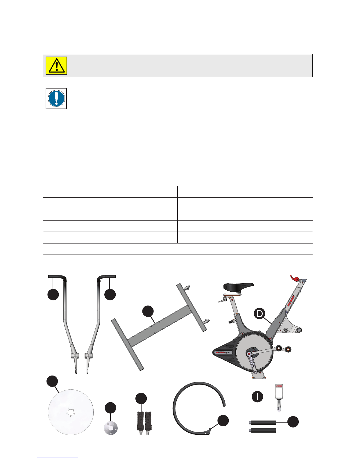
A - Left Handle (550832S/X) G - Pedal Set (555438)
B - Right Handle (550833S/X) H - Flywheel Guard & Cap (553101B/X & 555073)
C - Base Frame (550814G/X) I - M Series Computer
D - TBT Main Frame (550826PBC/XXC) J - Foot Rests (550834)
E - Flywheel (555003) K - M Series Computer
F - Hubcap (555005)
NOTE: Informs you about things we recommend you do or are aware of, before
performing the assembly. These notes are placed in the manual to aid you during a
certain procedure or to make you aware of any general mandatory actions or information.
WARNING: This symbol appearing throughout this manual means PAY ATTENTION! BE
ALERT! When you see this warning symbol, your safety is involved. It is being used to
call attention to POTENTIAL hazards that could result in personal injury or loss of life.
I
C
E
HJ
A
FG
B

LOOSE PARTS INVENTORY
L - Loose Parts Pack #1
L1 - 4 Acorn Nuts (555022)
L2 - 4 Aircraft Washers 7/16 (9384)
M - Loose Parts Pack #2
M1 - 1 Hex Nut M6x1 (9508)
M2 - 1 Hex Head Cap Screw M6x1 X 45 (9525)
M3 - 2 Flywheel Guard Clamps (555025)
N - Loose Parts Pack #3
N1 - 5 Socket Head Cap Screws M6x1 X 20 (9502)
N2 - 2 Large 5/16 Washers (9344)
N3 - 2 Aircraft Washers 3/8 (9355)
N4 - 2 Hex Elastic Lock Nuts M10x1.5 (9507)
N5 - 2 Hex Head Cap Screws M8x1.25 X 16 (9511)
N6 - 2 Socket Button Head Cap Screws M10x1.5 X 45 (9526)
N7 - 2 Nickel Plated Washers (115450)
N8 - 4 Bushings (305002)
N9 - 1 Loctite 242 (105550)
O - Loose Parts Pack #4
O1 - 2 Aluminum Caps with O-Rings (565005 & 565406)
O2 - 2 Foot Rest End Caps (555439)
O3 - 1 Shifter & Display Mt Cover (555082G/X)
Torque wrench (Minimum 47 Nm / 35 ft-lb) 16mm, or 5/8” crowfoot
6” extension for 3/8” drive 5mm Allen Wrench
15mm open-end wrench 6mm Allen Wrench
16mm, or 5/8” open-end wrench Paste or spray wax (used to clean after assembly)
#2 Phillips screwdriver Clean cloth
15mm crowfoot LPS #3 Heavy Duty Rust Inhibitor w/straw
2 - 10mm Wrenches Socket Wrench/Ratchet
13mm Socket 17mm Socket or Open-end Wrench
TOOLS YOU WILL NEED
NOTE: The substitution or modification of any part or component,
other than what is approved by Keiser, will void your warranty.
L1
L2
M2
M3
M1 N1
N2
N3
N4
N5
N6
N7 N9
N8 O3O1
O2

1 - Saddle 9 - Resistance Shifter
2 - Forward/Backward Seat Adjusment Handle 10 - Water Bottle Holder
3 - Up/Down Seat Adjustment 11 - Foot Rests
4 - Flywheel 12 - Eccentrics
5 - Belt Cover 13 - Crank Arm
6 - Base 14 - Platform Pedals
7 - Handles 15 - Transport Wheels
8 - Multi-Function Computer System
Total TBT Weight: 113 lbs (51.3 kg)
Footprint: Length 49 in (1245 mm) x Width 29 in (737mm)
KEISER M3 TBT
14
13
10
12
7
9
8
2
3
4
15
6
1
11
5

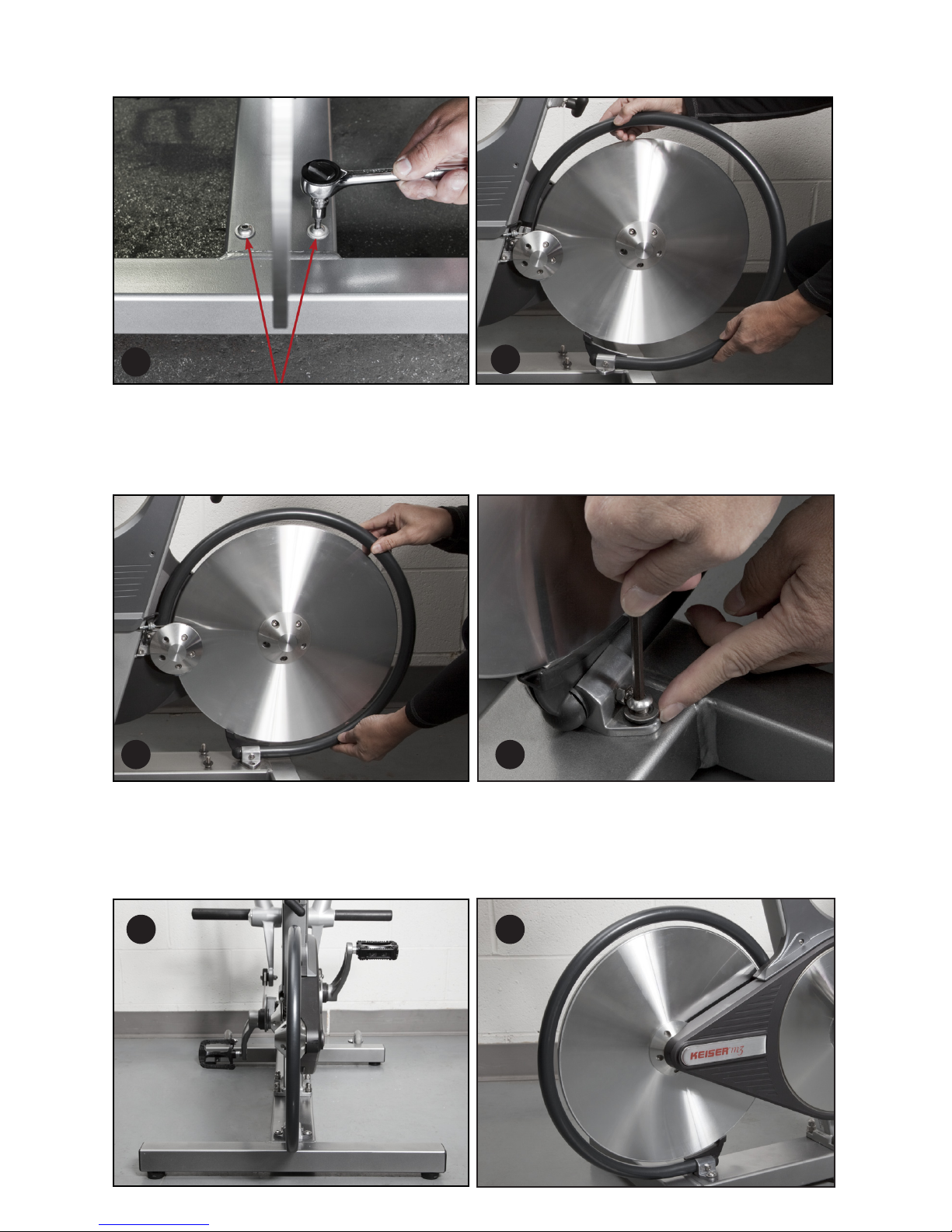
ASSEMBLING MAIN FRAME TO THE BASE FRAME
Step 1: Carefully lower the Main Frame onto the base frame over the base screws, with
the front of the TBT facing the transport wheels on the Base Frame. (Fig. 1)
Step 2: Insert one washer on each of the four base frame studs. (Fig. 1)
Step 3: Install the acorn nuts (L1) and the aircraft washers (L2) on the studs and hand
tighten Torque the acorn nuts with a 16mm or 5/8” crowfoot and torque wrench to
47 Nm (35 ft-lbs) using a 16mm, or 5/8 inch open-end wrench to hold in position. (Fig. 2)
ASSEMBLING PLASTIC COVER
Step 1: Obtain the #2 Phillips screwdriver and remove the screws from the plastic sweat
guard. (Fig. 3)
Step 2: Slide on the Platstic Cover and snap it over and align with the mounting holes of
the Sweat Guard. (Fig. 4)
Step 3: Insert and secure the screws removed in Step 1 using the #2 Phillips screwdriver.
(Fig. 5)
TBT ASSEMBLY
1 2
3 54

7
6
ASSEMBLING FLYWHEEL, HUB, AND HUB CAP
Step 1: Before starting the assembly of the ywheel, hub, and hub cap, make sure that
the shifter lever is in the downward position. (Fig. 6)
NOTE: Not following this step may scratch the ywheel.
Step 2: Remove the plastic wrapping from around the axle, hub, and hub cap. Remove
the hub cap and set it aside along with the ve socket head cap screws (N1). Remove
the plywood protector Remove partial of the ywheel from its foam envelope leaving the
foam envelope to grab the ywheel with.
Step 3: Carefully slide the ywheel between the two magnets (Fig 7. & Fig. 8) and onto the
hub at the same time. Make sure that the ywheel is ush against the hub and align the
screw holes.
NOTE: Use the foam envelope to handle the ywheel during assembly.
Step 4: Holding the ywheel in position with one hand, install the hubcap and align the
screw holes. Install the socket head cap screws (N1). Using the 5mm Allen wrench, tighten
the screws in a star pattern until snug (as shown in Fig. 9).
89

WARNING! Failing to install the pedals with Loctite 242, or crossing the threads
will damage them, and could result in serious injury to the user.
10
NOTE: Left pedal is LH threads
and right pedal is RH threads.
Step 2: With a clean cloth, wipe the
threaded area of the pedals. Apply
Loctite 242 to the pedal threads. Install
the pedals into the crank arms, use the
15mm open-end wrench to tighten.
Finish with the torque wrench, 15mm
crowfoot, and 6” extension. Torque
pedals to 47 Nm (35 ft-lbs) (Fig. 10).
ASSEMBLING PEDAL TO CRANK ARM
Step 1: Unwrap the pedal set and Loctite 242, obtain the Torque wrench, 15mm
crowfoot, 6” extension, and 15mm open-end wrench.
MOUNTING COMPUTER
Step 1: Obtain the #2 Phillips screwdriver and remove the computer mounting screw
from the display mount.
Step 2: Coil the computer cable into the computer mount cavity (Fig. 11).
Step 3: Slide the computer up into the two locking ears. Insert and secure the screw you
removed in Step 1 using the #2 Phillips screwdriver (Fig. 12).
11
12

MOUNTING HANDLES AND LINKS
ASSEMBLING FOOT REST
Step 1: Obtain both Foot Rests (J) and apply some Loctite 242 (N9) to the threads.
Step 2: Screw and hand tight both Foot Rests into the tapped holes on both sides of the
TBT (Fig. 17 - NEXT PAGE).
13 14
15 16
Step 1: Obtain the Left (A) or Right (B) Handle, and slide it over the pivot shaft as shown
(Fig. 13).
Step 2: While holding the Handle, secure the Large Washer (N2) and the Hex Head Cap
Screw (N5) using a ratchet and the 13mm socket. Torque the screw to 23 Nm (17 ft-lbs)
(Fig. 13 & 14).
Step 3: Align and assemble the Handle to the link as shown (Fig. 15). While holding the
6mm Allen Wrench on the Socket Button Head Cap Screw (N6), Tighten and torque the
Hex Elastic Lock Nut (N4) to 23 Nm (17 ft-lbs) using a 17mm socket and torque wrench.
Step 4: Insert the Aluminum Cap (O1) into the Handle (Fig. 16). Be careful not to damage
the attached O-Ring.
Step 5: Repeat Step 2 and Step 4 for the Handle and Link on the other side.

17 18
Step 3: Using the ratchet and a 6” extension, tighten and torque the Foot Rests to 47 Nm
(35 ft-lbs) (Fig.18).
19
Step 4: Insert the Foot Rest End Caps (O2)
intoboth Foot Rests (Fig. 19).
FLYWHEEL GUARD INSTALLATION
Step 1: Make sure to have all parts and tools present prior to assembly.
Step 2: Assemble the brackets (B) to the tube (C) With the bolt and nut (A) nger tight.
PARTS INVENTORY
A) Bolt and Nut B) Brackets C) Tube
A
B
C
20
Step 3 (Next Page): Make sure the ywheel is centered in the middle of the 2x4 tube of the
base frame. Remove the two (6mm allen) screws and washers from the base frame. These
screws will be used to mount the ywheel guard in step 6.
21
Step 5: Swing the tube over the ywheel, aligning the tube centered with the ywheel.
Step 6: Tighten the brackets to the base frame with the screws and washers that were
removed in step three. Do not fully tighten the bolts.
Step 7: By not fully tightening the bolts, the brackets allow the tube to move left to right to
some degree. Center the tube with as much clearance as possible from the ywheel, then
fully tighten all the bolts. Make sure the tube is centered over the ywheel. The ywheel
must be completely hidden behind the tube as shown below.
Step 4: Place the assembled ywheel guard over the holes and hold the tube guard as
shown, to the left of the ywheel. Place the open end of the tube guard over the casting.
22
24
26 27
25
23
Indice
Altri manuali Keiser Cyclette

Keiser
Keiser M3 Manuale utente

Keiser
Keiser M3 Manuale utente

Keiser
Keiser M SERIES Istruzioni per l'installazione e il funzionamento

Keiser
Keiser M3X Manuale utente

Keiser
Keiser M SERIES Istruzioni per l'installazione e il funzionamento

Keiser
Keiser M3i lite Manuale utente

Keiser
Keiser REAR WHEEL DRIVE BIKE Manuale utente

Keiser
Keiser M3i lite Manuale utente

Keiser
Keiser M3 Guida alla risoluzione dei problemi

Keiser
Keiser M3 Manuale utente


 Manuale utente")


