M-Elec ADB-2F40B Manuale utente
2-
p
hase Ste
pp
in
g
Motor Drive
r
ADB-2F40B
Instructions Manual
(For designers' use)
MN0225-1
Please ensure to read and understand this
Instructions Manual before using the product.
Please keep this Instructions Manual at hand
so that it is always available for reference.

ADB-2F40B
Instructions Manual
Introduction
This Instructions Manual describes the safe and proper method of handing
"2-phase Stepping Motor Driver ADB-2F40B" with emphasis on the specifications,
assuming that our readers are engaged in designing of control devices
incorporating stepping motors.
Please ensure to read and understand this Instructions Manual
before using the product.
Please keep this Instructions Manual at hand
so that it is always available for reference.
-2-

ADB-2F40B
Instructions Manual
Descriptions in this manual on safety matters:
This product must be operated and used properly.
Otherwise , or when it is operated and used erroneously, unforeseen accidents
may occur, causing physical injuries or property damages.
Majority of these accidents can be avoided if you are well informed of
hazardous circumstances in advance.
Consequently, this instructions manual describes all the hazardous and
dangerous circumstances and situations which can be foreseen and anticipated
as well as necessary precautions.
All the above descriptions are being titled by the following symbol-marks and
signal-words, namely:
Represents warnings ignorance of which can cause accidents
involving fatal or serious physical injuries.
Represents cautions ignorance of which can cause accidents
involving minor physical injuries or property damages.
-3-

ADB-2F40B
Instructions Manual
Introduction
Descriptions in this manual on safety matters:
CONTENTS PAGE
1. Safety
1-1. Safety Precautions 6
1-2. Safety Information for Handling 7
2. Overview
2-1. Characteristics 10
2-2. Product Configuration 10
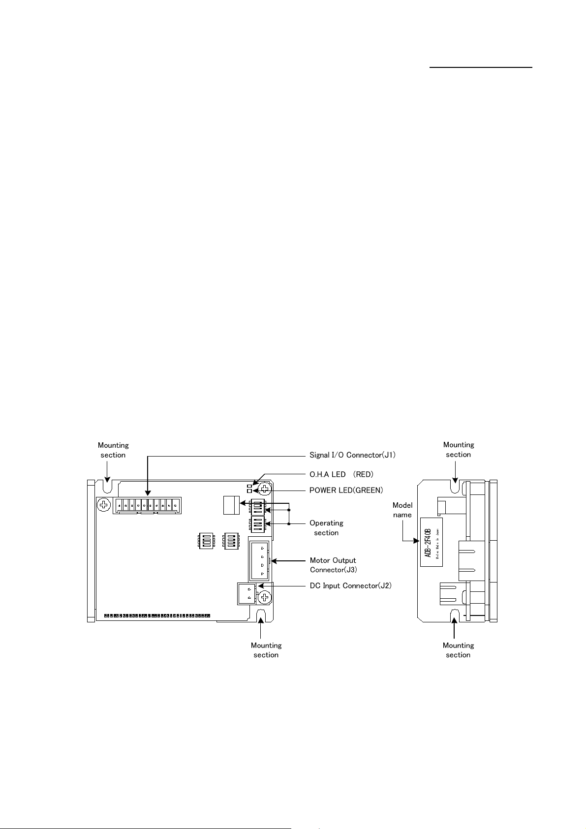
2-3. Appearance 10
3. Name and Function of Each Section
3-1. Signal I/O Connector(J1) 11
3-2. DC Input/Motor Output Connector(J2, J3) 12
3-3. POWER LED 12
3-4. O.H.A LED 12
3-5. Operating Section 13
4. Name and Function of Each Section
4-1. Setting STEP TABLE switch and STEP ANGLE SELECT switch 14
4-2. Setting HOLD CURRENT SELECT switch 15
4-3. Setting DRIVE CURRENT SELECT switch 16
4-4. Setting PULSE INPUT TYPE SELECT switch 17
4-5. Setting HOLD SWITCHING TIME SELECT switch 18
5. Installation
5-1. Conditions for Installation 19
5-2. Mounting Method 20
6. Connection
6-1. Overview of Connection Configuration 21
6-2. Connecting Signal I/O Connector(J1) 22
6-3. Connecting DC Input/Motor Output Connector(J2, J3) 23
6-4. Inputting Power 24
7. Confirmation of Setting and Connection
7-1. Check Points 25
-4-

ADB-2F40B
Instructions Manual
PAGE
8. Maintenance and Check-up
8-1. Maintenance and Check-up 26
8-2. Troubleshooting 27
9. Storing and Disposal
9-1. Storing 28
9-2. Disposal 28
10. Specifications
10-1. General Specifications 29
10-2. I/O Signal
(1) Example Circuit Connection 30
(2) Drive pulse input (CW,CCW) 31
(3) Motor excitation stop input (M.F) 32
(4) Phase signal output (P.O) 33
(5) Overheat alarm signal output and overheat alarm LED (O.H.A) 34
10-3. Dimensions 35
10-4. Applicable Motors 36
10-5. Torque Characteristics 37
10-6. Conforming to Europe standards 43
The main parts which revised by this manual
-5-

ADB-2F40B
Instructions Manual
1.Safety
1-1.Safety Precautions
(1) This product is not designed or manufactured for application for equipment
requiring high level of reliability such as equipment related to nuclear
energy, aeronautics-related equipment, automobiles, ships, medical appliances
directly handling the human body and equipment that might seriously affect
properties.
(2) Do not use or keep the product in explosive or corrosive environments,
in the presence of flammable gases, locations subjected to splashing water,
fine particles, soot, steam, or exposed to radiation or direct sunshine.
Doing so may cause injury or fire.
(3) For the driver's power supply, use a DC power supply with reinforced insulation
on its primary and secondary sides.
Failure to do so may cause electric shock.
(4) This product is designed for use within machinery, so it should be installed
within an enclosure.
Failure to do so may cause injury.
(5) Do not transport, move, install the product, perform connections or inspections
when the power is on.
Doing so may cause electric shock, injury or fire.
(6) Only qualified personnel are allowed to transport, move, install the product,
perform connections or inspections.
Failure to do so may cause injury or fire.
(7) Do not touch the driver during operation or immediately after stopping.
Doing so may cause burn on the skin due to overheating of the driver.
(8) Ensure to use this product according to the method specified
in the Instructions Manual and within the specifications.
(9) Depending on the operational conditions, the stepping motor may step out when
it is on holding-state or driving-state.
In particular, the load in transport may fall if the motor steps out on the
vertical drive (such as the Z-axis).
Start operation after test run for deliberate confirmation of operation.
(10) Provide fail-safe measures so that the entire system may operate in a safe
mode even in cases of the external power supply failure, disconnection of the
signal line, or any failure on the driver.
-6-

ADB-2F40B
Instructions Manual
1-2.Safety Information for Handling
●Overall:
Do not touch the driver during operation
or immediately after stopping.
it may cause burn on the skin due to
overheating of the driver.
●When setting up the STEP ANGLE SELECT switch:
Erroneous setting may cause breakage of
the machine or injury due to unexpected
rotation of the motor.
Ensure correct setting.
●When setting up the HOLD CURRENT SELECT switch:
A high setting value may cause burn on the
skin due to overheating of the motor.
Do not select a high value beyond the
required.
●When setting up the DRIVE CURRENT SELECT switch:
Erroneous setting may cause burn on the
skin, injury or damage to the motor due to
overheating of the motor.
Ensure correct setting.
-7-

ADB-2F40B
Instructions Manual
●When setting up the PULSE INPUT TYPE SELECT switch:
Erroneous setting may cause breakage of
the machine or injury due to unexpected
rotation of the motor.
Ensure correct setting.
●When installing:
Overheating may cause fire.
Mount it on a noncombustible member.
Keep it away from combustibles.
●When connecting the DC Input/Motor Output Connectors (J2, J3):
Erroneous connection may cause
breakage of the motor or the driver.
Correctly connect the DC Input/Motor
output connector.
●When inputting power:
Breakage of the machine or injury is
apprehended due to unexpected behavior of
the motor. Maintain the state where
emergency stop is enabled at any time.
-8-

ADB-2F40B
Instructions Manual
●When inputting the motor excitation stop (M.F) signal:
Deterioration of the holding power with
the motor may cause breakage of the machine
or injury.
Check safety before inputting.
●When the overheat alarm (O.H.A) signal is output:
Overheating may cause fire.
Stop operation upon output of this signal.
●When the overheat alarm (O.H.A) LED comes on:
Overheating may cause fire.
Stop operation when this LED comes on.
●When performing maintenance and checking:
Injury or fire is apprehended due to
unexpected behavior.
Do not replace fuse.
Do not disassemble, repair or modify.
-9-
ADB-2F40B
Instructions Manual
2.
O
verv
i
ew
2-1.Characteristics
ADB-2F40B is a driver for a 2-phase stepping motor with DC+24V input.
Driving method is bipolar constant current type.
It can drive a 2-phase stepping motor of bipolar winding ranging from
Step angles can be selected from fourteen step angles ranging from 1 division to
HOLD CURRENT and DRIVE CURRENT can be set up.
2-2.Product Configuration
The product consists of the main frame and the accessories.
●ADB-2F40B One unit
●Housing for J1 (51103-1000:Molex) One unit (accessory)
●Housing for J2 (51067-0200:Molex) One unit (accessory)
●Housing for J3 (51067-0400:Molex) One unit (accessory)
●Contact for J1 (50351-8100:Molex) 12 contacts (accessories,2 for spares
)
●Contact for J2,J3 (50217-9101:Molex) 8 contacts (accessories,2 for spares
)
2-3.Appearance
-10-
Indice
Altri manuali M-Elec Unità di controllo


Manuali Unità di controllo popolari di altre marche

Festo
Festo Compact Performance CP-FB6-E Manuale elenco delle parti

Elo TouchSystems
Elo TouchSystems DMS-SA19P-EXTME Manuale utente

JS Automation
JS Automation MPC3034A Manuale utente

JAUDT
JAUDT SW GII 6406 Series Guida rapida

Spektrum
Spektrum Air Module System Manuale utente

BOC Edwards
BOC Edwards Q Series Manuale utente


