
METREL MA 2067 Manuale utente
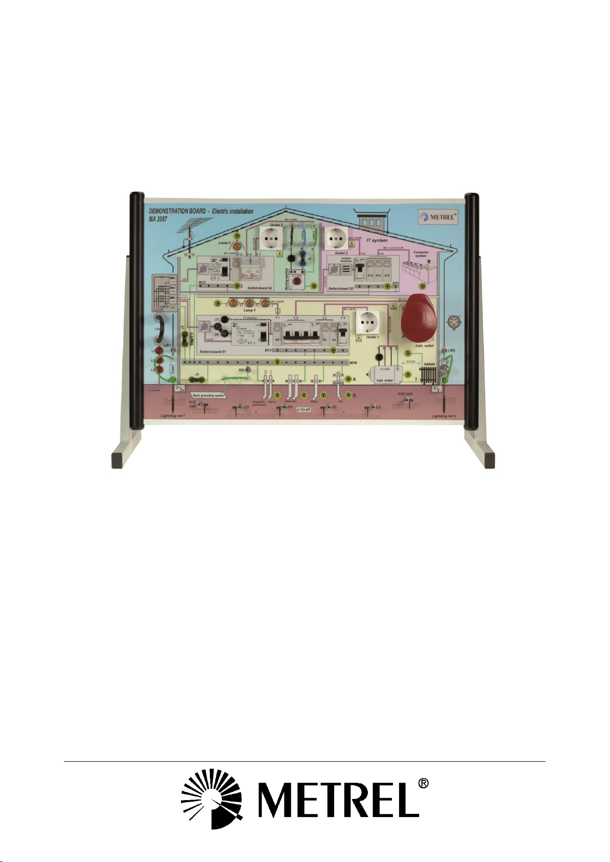
Demonstration board
MA 2067
Instruction manual
Version 1.4.5, Code no. 20 750 789
2
Distributor:
Manufacturer:
Metrel d.d.
Ljubljanska cesta 77
SI-1354 Horjul
Slovenia
https://www.metrel.si
Mark on your equipment certifies that it meets requirements of all subjected EU
regulations.
Hereby, Metrel d.d. declares that the MA 2067 is in compliance with subjected
EU directive. The full text of the EU declaration of conformity is available at the
following internet address https://www.metrel.si/DoC.
© 2022 METREL
The trade names Metrel®, Smartec®, Eurotest®, Auto Sequence®are trademarks registered in Europe and other
countries.
No part of this publication may be reproduced or utilized in any form or by any means without
permission in writing from METREL.

Demonstration board MA 2067 Contents
3
1. Introduction...........................................................................................................4
2. Description of the demonstration board.............................................................5
2.1 Front panel..........................................................................................................5
2.2 Command part (back side of the demonstration board)......................................7
2.3 Demonstration board support..............................................................................8
3. Technical data.......................................................................................................8
4. Connection to mains voltage...............................................................................9
5. List of possible measurements on the board...................................................11
6. Simulation of errors............................................................................................13
7. List of instruments to be used in combination with the board.......................15
8. Maintenance........................................................................................................16
8.1 Cleaning............................................................................................................16
8.2 Service..............................................................................................................16
9. Standard set........................................................................................................17
10.Options................................................................................................................17

Demonstration board MA 2067 Introduction
4
1. Introduction
Demonstration board MA 2067 is a school facility. It simulates real low voltage electro-
installation. Major elements like fuses, RCD protection switches, outlets etc. are
incorporated.
The board is designed to be used in middle level electrical schools in order to improve
practical and theoretical knowledge of listeners on electro-installation, on possible errors
of installation and on how to carry out different measurements of electro-installation. It is
aimed as well to be used at sale-demonstration rooms for presentation of electro-
installation testers and their application.
Demonstration board enables demonstration on three earthing systems: TT, NT, IT.
It performs the following major activities:
Education of students / pupils on low voltage electro-installation.
Practical training and courses about measurements on low voltage electro-
installation and simulation of errors both, on electro-installation and on connected
appliances.
Demonstration on how to use different measurement instruments.
The board's plug is prepared to be connected to three-phase mains installation or to
one-phase installation with help of one-phase adapter. The board can be used in
horizontal position for small groups of listeners or in vertical position for demonstration
in a class, presentation at seminar, exhibition etc.
Demonstration board MA2067 Description of the demonstration board
5
2. Description of the demonstration board
2.1 Front panel
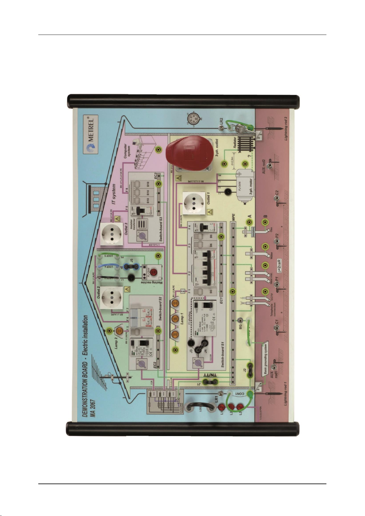
Fig.1. Front panel

Demonstration board MA2067 Description of the demonstration board
6
Meaning of abbreviations on front panel
J1 to J5 ...........................Jumper 1 to Jumper 5
LR 1 ................................Lightning rod 1
LR 2 ................................Lightning rod 2
BG ..................................Basic Grounding
AUX rod 1 .......................AUXiliary rod 1
AUX rod 2 .......................AUXiliary rod 2
C1 ...................................Current probe 1
C2 ...................................Current probe 2
P1 ...................................Potential probe 1
P2 ...................................Potential probe 2
MPE ...............................Main Potential Equilizing
EC1 to EC3 ....................Earth Collector 1 to Earth Collector 3
F1 ...................................Fuse –Lamp 1
F2 ...................................Fuse –3-phase outlet
F3 ...................................Fuse –3-phase motor
F4 ...................................Fuse –Outlet 1
F5 ...................................Fuse –Lamp 2
F6 ...................................Fuse –Washing machine
F7 ...................................Fuse –Outlet 2
F8 ...................................Fuse –Outlet 3
F9 ...................................Fuse –Computer system
B1 to B9 ..........................Branch 1 to Branch 9
Demonstration board MA2067 Description of the demonstration board
7
2.2 Command part (back side of the demonstration board)
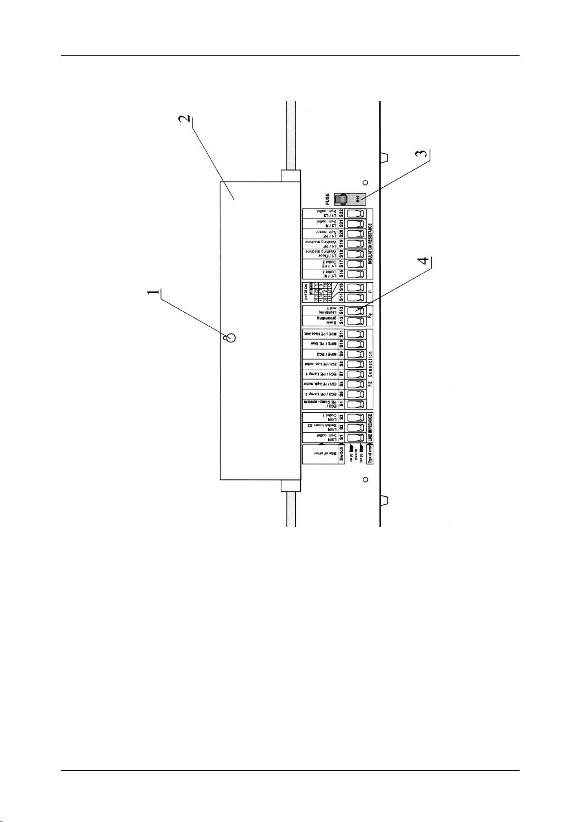
Fig.2. Command part (protection screen lifted up)
Legend:
1…Key lock for protection screen locking
2…Protection screen to cover command part
3…Automatic fuse which:
protects demonstration board and a user of the board in case of a fault on line L1
(simulated errors in command part excluded)
serves for general on/off of the board
serves for reset (reswitching on) of the board in case protection electronic inside
the board trips the board due to a certain fault (simulated errors in command part
excluded)
4…Switches for simulation of different errors
Demonstration board MA 2067 Technical data
8
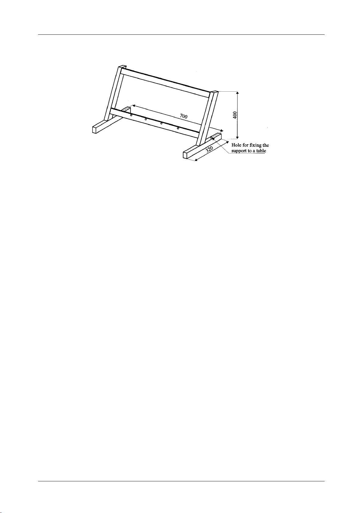
2.3 Demonstration board support
Fig.3. Support
Use the support in case demonstration board is to be used in vertical position for
demonstration to a wider audience. It is possible to fix the support to a table using two
screws (which are not a part of the standard set) in order to improve stability of
demonstration board (when pulling out and pushing in test plugs).
3. Technical data
Mains connection .................three-phase (4m) type 3P+N+PE or one-phase type, using
one-phase adapter (2m)
Width ...................................680 mm
Height ..................................450 mm
Mass ....................................12,5 kg approx.
Fixing to a table ...................by means of two screws (distance between fixing holes is
700 mm)
Respected standards ...........EN 61010-1 (safety)
EN 50081-1 (EMC)
EN 50082-1 (EMC)
VDE 0100 (construction of electro-installation)
Test sockets .........................one-phase with PE terminal
three-phase (3L+N+PE)
Protection classification........(PE terminal connected to metal housing)
Demonstration board MA 2067 Connection to mains voltage
9
4. Connection to mains voltage
Before connecting the Demonstration board to mains installation, the following must be
checked by the operator:
That PE terminal is present at mains outlet which is to be used for connection of the
board and that there are no damages noticed at the outlet (mechanical damages,
broken contacts etc.)
That there are no damages present at board's plug and at board itself (damaged
outlets, mechanical damages of other elements etc.)
That there is an RCD protection switch ∆=30 mA involved in mains installation to be
used for supplying of the board (recommendation)
Attention!
The board is allowed to be used only in presence of properly educated person-
teacher, when using it in schools.
Use only attached, original jumpers (defined distance between two ends) for
carrying out required connections on front panel of the board.
Use the test outlets on front panel for test purpose only and not for supplying
different loads (radio, cooker, lamp etc.) because the components inside the
board (wiring, switches, contacts, resistors etc.) are dimensioned for test
purpose only.
Do not short accessible contacts at one-phase or three-phase outlets.
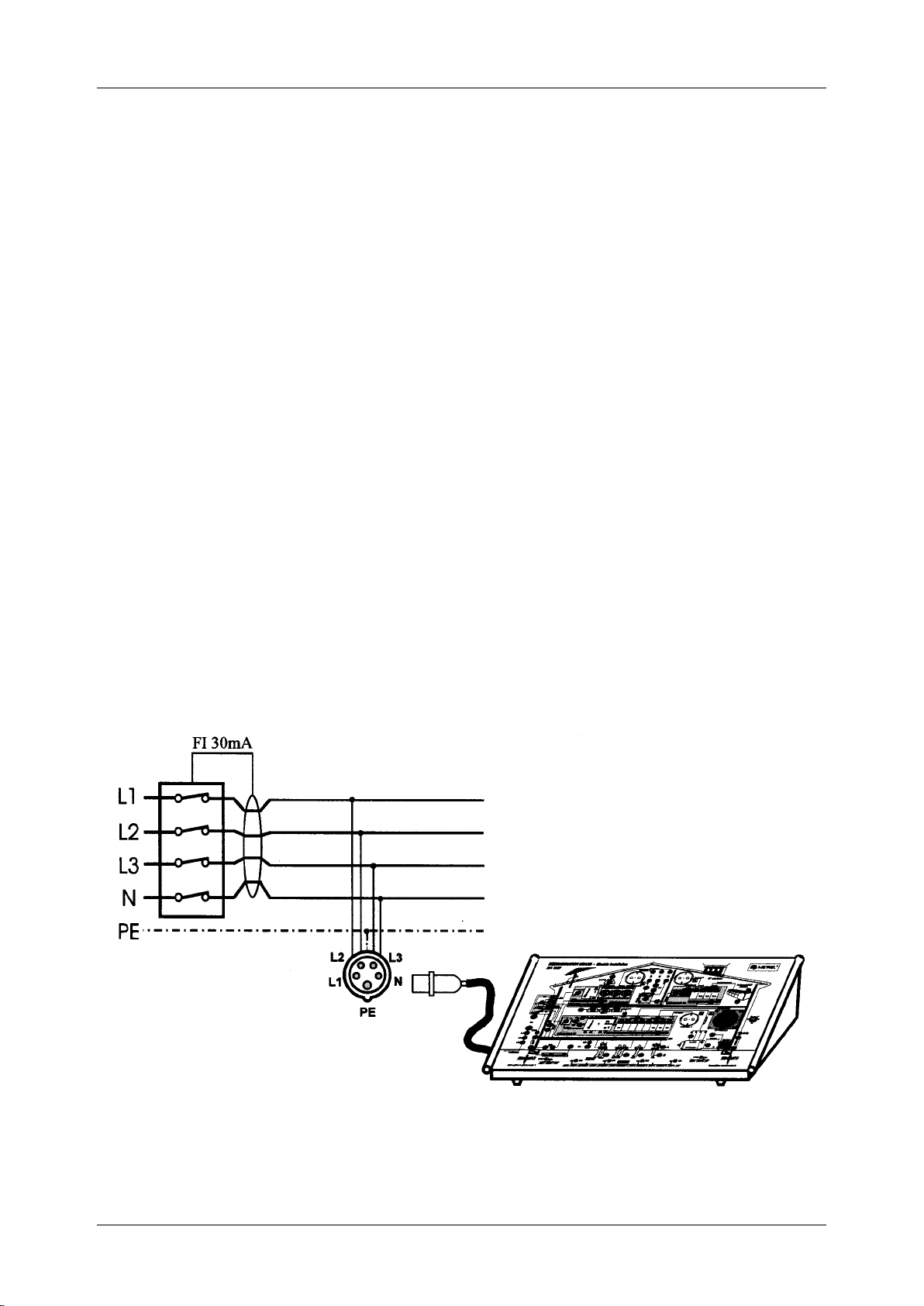
Connection to 3-phase outlet
Fig.4. Connection of the Demonstration board to 3-phase outlet
Demonstration board MA 2067 Connection to mains voltage
10
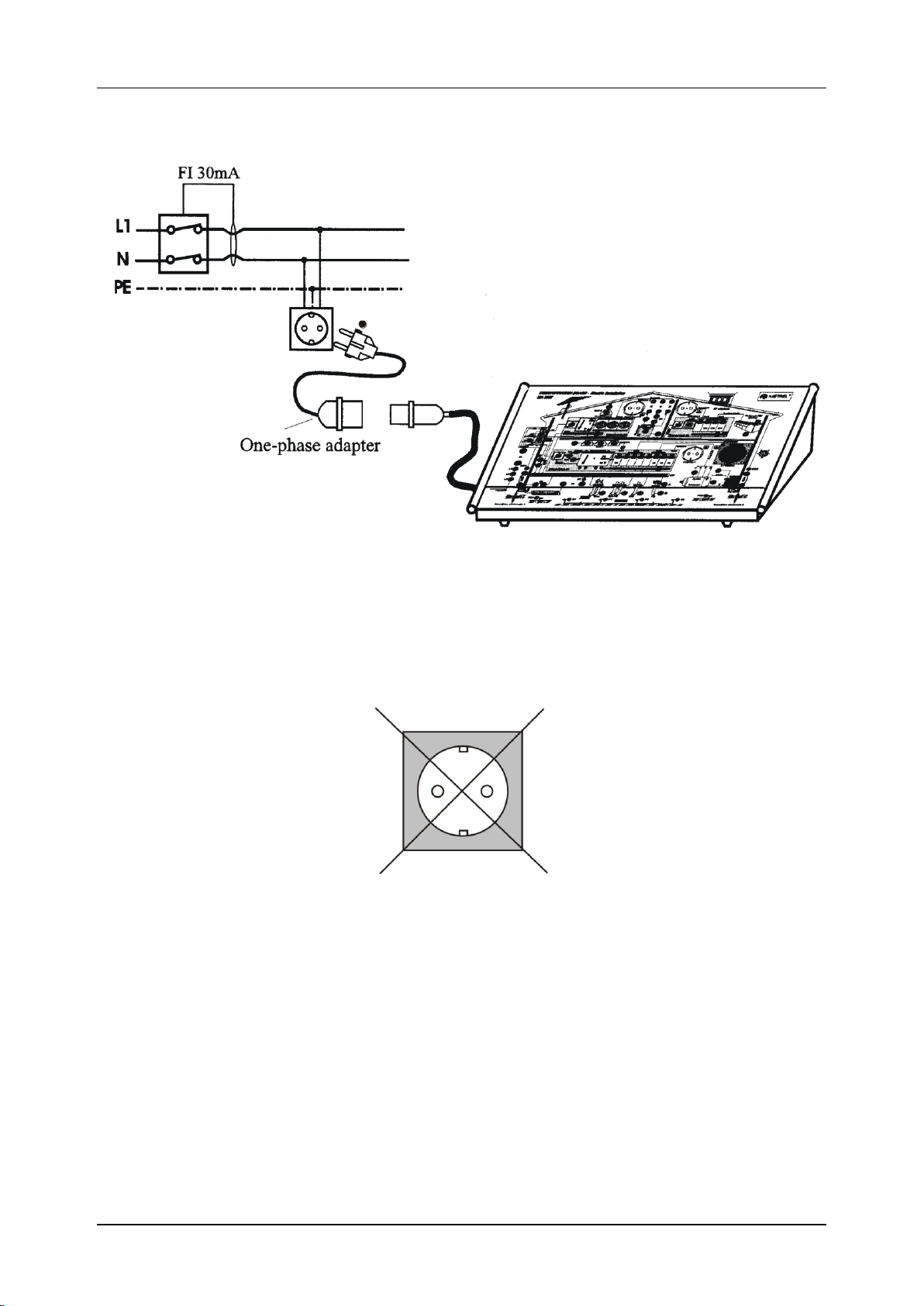
Connection to one-phase outlet
Phase mark
Fig.5. Connection of the Demonstration board to one-phase outlet
Not intended for insulation tests
Note:
The equipment contains a special input protection circuit. Please ensure minimum of 10
s between unplugging the demo board and plugging it in again. This will enable that the
protection circuit is working correctly.
Indice
Altri manuali METREL Scheda madre


Manuali Scheda madre popolari di altre marche


Telit Wireless Solutions
Telit Wireless Solutions SL869-3DR Manuale utente

Gigabyte
Gigabyte GA-9IVDT Manuale utente

Texas Instruments
Texas Instruments ADS8372EVM Manuale utente

Commell
Commell MS-C73 Manuale utente

IBT Technologies
IBT Technologies MB860 Manuale utente

Nvidia
Nvidia TEGRA DG-04927-001_V01 Manuale utente


