— 4 — —5— — 6—
Note
Before tightening the screws into the wall, make sure the screw head
and shank size are suitable by inserting the screw into one of the
keyhole-shaped apertures of the wall mounting plates.
5. Connector Description
Power Connector
Connect the 12 to 48 VDC LPS or Class 2 power line to the IA3341’s
terminal block. If the power is properly supplied, the Power LED will
light up. The OS is ready when the Ready LED glows a solid green.
Grounding the IA3341
Grounding and wire routing help limit the effects of noise due to
electromagnetic interference (EMI). Run the ground connection from the
ground screw to the grounding surface prior to connecting the power.
ATTENTION
This product is intended to be mounted to a well-grounded mounting
surface, such as a metal panel.
SG
12-48 VDC
Power Input
SG: The Shielded Ground (sometimes called
Protected Ground) contact is the bottom
contact of the 3-pin power terminal block
connector when viewed from the angle
shown here. Connect the SG wire to an
appropriate grounded metal surface.
Ethernet Ports
The two 10/100 Mbps Ethernet ports (LAN 1 and LAN 2) use RJ45
connectors.
Pin Signal
1 ETx+
2 ETx-
3 ERx+
6 ERx-
18
Serial Ports
The IA3341’s serial ports use DB9 male connectors. Each port can be
configured by software for RS-232, RS-422, or RS-485. The pin
assignments for the ports are shown in the following table:
Pin RS-232 RS-422 RS-485
(4-wire)
RS-485
(2-wire)
1 DCD TxDA(-) TxDA(-) ---
2 RxD TxDB(+) TxDB(+) ---
3 TxD RxDB(+) RxDB(+) DataB(+)
4 DTR RxDA(-) RxDA(-) DataA(-)
5 GND GND GND GND
6 DSR --- --- ---
7 RTS --- --- ---
8 CTS --- --- ---
12345
6789
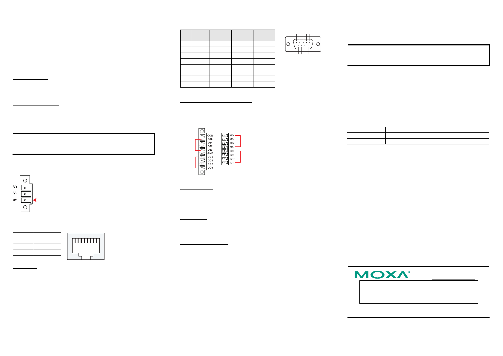
DI/DO/AI/Thermocouple Channels
The IA3341 has four digital input channels and four digital output
channels located on the front panel. Two analog input channels and two
thermocouple channels are also provided on the top panel. See the figures
below for the pinout description.
DI x 4
DO x 4
AI x 2
Thermocouple x 2
SD Card Socket
The IA3341 comes with an SD card socket for storage expansion, but
CompactFlash hot swap and PnP are not supported. This means that you
must disconnect the power source before inserting or removing the SD
card.
Console Port
The IA3341’s console port is a 4-pin pin-header RS-232 port. It is
designed for serial console terminals, which are useful for identifying the
boot up message, or for debugging when the system cannot be booted up.
Reset to Default Button
The IA3341 has one Reset to Default button located on the top panel of
the housing. Depress the button for 5 seconds until the Ready LED
blinks five times. The system will boot up and run the Reset to Default
procedure.
USB
The IA3341 has one USB 2.0 full speed host (OHCI) that uses a type A
connector. The port supports keyboard and mouse, and can also be used
to connect a FlashDisk for storing large amounts of data.
Real Time Clock
The IA3341’s real time clock is powered by a lithium battery. We
strongly recommend that you do not replace the lithium battery without
help from a qualified Moxa support engineer. If you need to change the
battery, contact the Moxa RMA service team.
ATTENTION
There is a risk of explosion if the battery is replaced by an incorrect type
of battery.
6. Powering on the IA3341
To power on the IA3341, connect the power source to the terminal block
located on the top panel. Note that the Shielded Ground wire should be
connected to the right most pin of the terminal block. It takes about 30
seconds for the system to boot up. Once the system is ready, the Ready
LED will light up.
The IA3341 computer comes with two network interfaces. The default IP
addresses and netmasks of the network interfaces are as follows:
Default IP Address Netmask
LAN 1 DHCP DHCP
LAN 2 192.168.4.127 255.255.255.0
7. Configuring the Ethernet Interface
If you use the console cable for first-time configuration of the Network
settings, use the following commands to edit the interface file:
Step 1:
#ifdown –a
//Disable LAN1/LAN2 interface first, before you reconfigure the LAN
settings. LAN 1 = eth0, LAN 2= eth1//
#vi /etc/network/interfaces
//check the LAN interface first//
Step 2:
After the boot setting of the LAN interface has been modified, use the
following command to activate the LAN settings immediately:
#sync; ifup –a
Click here for online support:
www.moxa.com/support
The Americas: +1-714-528-6777 (toll-free: 1-888-669-2872)
Europe: +49-89-3 70 03 99-0
Asia-Pacific: +886-2-8919-1230
China: +86-21-5258-9955 (toll-free: 800-820-5036)
©2010 Moxa Inc. All rights reserved.
Reproduction without permission is prohibited.


