National Instruments NI USB-7845R Manuale utente
USER MANUAL
NI USB-7845R OEM
R Series for USB Multifunction RIO with Kintex-7 70T FPGA
Français Deutsch 日本語 한국어 简体中文
ni.com/manuals
This document provides dimensions, connectivity information, and pinouts for the National
Instruments USB-7845R OEM device.
Caution National Instruments makes no product safety, electromagnetic
compatibility (EMC), or CE marking compliance claims for NI USB-7845R OEM
device. The end-product supplier is responsible for conformity to any and all
compliance requirements.
Caution Do not operate the NI USB-7845R OEM device in a manner not specified
in this user manual. Product misuse can result in a hazard. You can compromise the
safety protection built into the product if the product is damaged in any way. If the
product is damaged, return it to National Instruments for repair.
Hardware Overview
The following high-level block diagram represents the NI USB-7845R OEM device.

Figure 1. NI USB-7845R OEM Device Block Diagram
Device
Temperature
Overvoltage
Protection
Overvoltage
Protection
FPGA
Temperature
40 MHz
OSC
AO (x8)
USB
NI ASICKintex-7
FPGA
NI USB-7845R OEM
Flash
Memory
DIO
+5 V
Reference
DAC AO
ADC AI
CONNECTOR 1 CONNECTOR 2 CONNECTOR 3CONNECTOR 0
Data/
Address/
Control
AI (x8)
INA
DIO (x16)
DIO (x16)
DIO (x16)
Overvoltage
Protection
Overvoltage
Protection
Overvoltage
Protection
2| ni.com | NI USB-7845ROEM User Manual

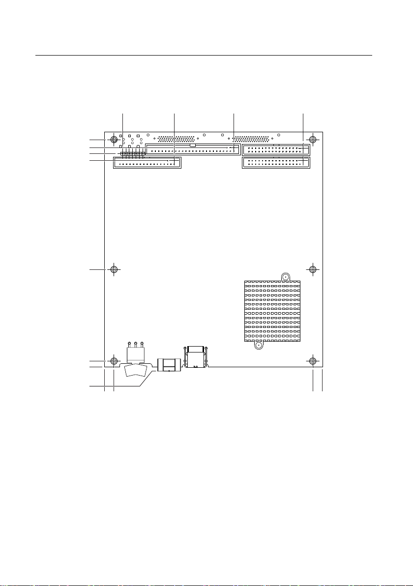
Parts Locator
7
8
1
2
3
4
6
5
1. USB Connector
2. Power Supply Connector
3. Power Switch
4. External LED Attachments
5. Connector 0 (Analog)
6. Connector 1 (Digital)
7. Connector 2 (Digital)
8. Connector 3 (Digital)
NI USB-7845R OEM Device Components
The following table lists the interfacing components on the NI USB-7845R OEM device and
the component manufacturers.
Table 1. NI USB-7845R OEM Device Components
Components Reference Designator Manufacturer
LEDs DS2, DS5, DS7, DS8, DS10 SunLED (XZBB54W-1TN)
DS4 Everlight Electronic (QTLP630C-2 T/R)
USB connector J5 Tyco (292304-1)
Power connector J1, J2, & J9 Phoenix Contact (1727566)
Power switch SW2 C&K (E101J1AQE2)
The following table lists and describes the I/O connectors on the NI USB-7845R OEM device.
Refer to the connector manufacturer for information about using and matching these
connectors.
NI USB-7845ROEM User Manual | © National Instruments | 3

Table 2. NI USB-7845R OEM Device Connectors
Connector Description Reference Designator Manufacturer
AI, AO 50-position header P2 3M (N2550-6002RB)
DIO 34-position header J9 3M (N2534-6002RB)
External LED 7-position header E1 FCI 68000-107LF
4| ni.com | NI USB-7845ROEM User Manual
Dimensions
2X .175 (4.45)
2X 2.863 (72.72)
2X 6.055 (153.81)
6.263 (159.08)
2X 6.675 (169.55)
.119 (3.02)
.000 (0)
2X 6.435 (163.46)
3X .285 (7.24)
3X 6.115 (155.32)
6.400 (162.56)
2.055 (52.19)
3.797 (96.44)
2X 5.838 (148.29)
.000 (0)
0.285 (7.24)
NI USB-7845ROEM User Manual | © National Instruments | 5
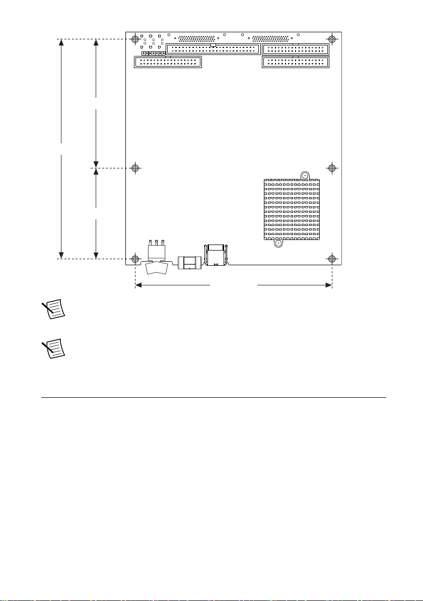
5.830 (148.08)
2.688 (68.28)
6.500 (165.1)
3.812 (96.82)
Note Visit ni.com/dimensions for more information about the dimensions of
the NI USB-7845R OEM device, including two-dimensional drawings and three-
dimensional models.
Note The NI USB-7845R OEM device has plated mounting holes that can act as
chassis ground.
Connecting the NI USB-7845R OEM Device
The NI USB-7845R OEM device provides connections for eight analog input (AI) channels,
eight analog output (AO) channels, and forty-eight digital input/output (DIO) channels, as
shown in Figure 2.
6| ni.com | NI USB-7845ROEM User Manual
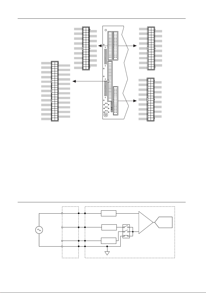
Figure 2. NI USB-7845R OEM Device Pinout
DIO0
DIO1
DIO2
DIO3
DIO4
DIO5
DIO6
DIO7
DIO8
DIO9
DIO10
DIO11
DIO12
DIO13
DIO14
DIO15
GND
GND
GND
GND
GND
GND
GND
GND
GND
GND
GND
GND
GND
GND
GND
GND
GND
GND
1
3
5
7
9
11
13
15
17
19
21
23
25
27
29
31
33
2
4
6
9
10
12
14
16
18
20
22
24
26
28
30
32
34
Connector 1
DIO0
DIO1
DIO2
DIO3
DIO4
DIO5
DIO6
DIO7
DIO8
DIO9
DIO10
DIO11
DIO12
DIO13
DIO14
DIO15
GND
GND
GND
GND
GND
GND
GND
GND
GND
GND
GND
GND
GND
GND
GND
GND
GND
GND
1
3
5
7
9
11
13
15
17
19
21
23
25
27
29
31
33
2
4
6
9
10
12
14
16
18
20
22
24
26
28
30
32
34
Connector 3
GND
GND
GND
GND
GND
GND
GND
GND
GND
GND
GND
GND
GND
GND
GND
GND
GND
7
9
11
13
15
17
19
21
23
25
27
29
31
33
9
10
12
14
16
18
20
22
24
26
28
30
32
34
DIO0
DIO1
DIO2
DIO3
DIO4
DIO5
DIO6
DIO7
DIO8
DIO9
DIO10
DIO11
DIO12
DIO13
DIO14
DIO15
GND
1
3
5
2
4
6
Connector 2
Connector 0
AI0-
AIGND
AI1-
AIGND
AI2-
AIGND
AI3-
AIGND
AI4-
AIGND
AI5-
AIGND
AI6-
AIGND
AI7-
AISENSE
AO0
AO1
AO2
AO3
AO4
AO5
AO6
AO7
+5V
AI0+
AIGND
AI1+
AIGND
AI2+
AIGND
AI3+
AIGND
AI4+
AIGND
AI5+
AIGND
AI6+
AIGND
AI7+
AIGND
AOGND
AOGND
AOGND
AOGND
AOGND
AOGND
AOGND
AOGND
+5V 50
48
46
44
42
40
38
36
34
32
30
28
26
24
22
20
18
16
14
12
10
8
6
4
2
49
47
45
43
41
39
37
35
33
31
29
27
25
23
21
19
17
15
13
11
9
7
5
3
1
Analog Input
The NI USB-7845R OEM device provides connections for eight AI channels. Each channel
has an AI+ pin, AI- pin, and AIGND pin to which you can connect both single-ended or
differential voltage signals. Use the AISENSE pin to connect non-referenced single-ended
signals.
Connecting Single-Ended Voltage Signals
To connect referenced single-ended voltage signals to the NI USB-7845R OEM device, you
must connect the voltage ground signal to AI GND in order to keep the common-mode voltage
in the specified range, as shown in Figure 3.
Figure 3. Connecting Referenced Single-Ended Signals to the NI USB-7845R OEM
Device
PGIA ADC
AI+
NI USB-7845R OEM
Connection
Accessory
AISENSE
AIGND
V1
+
–
Overvoltage
Protection
AI– Overvoltage
Protection
Overvoltage
Protection
NI USB-7845ROEM User Manual | © National Instruments | 7
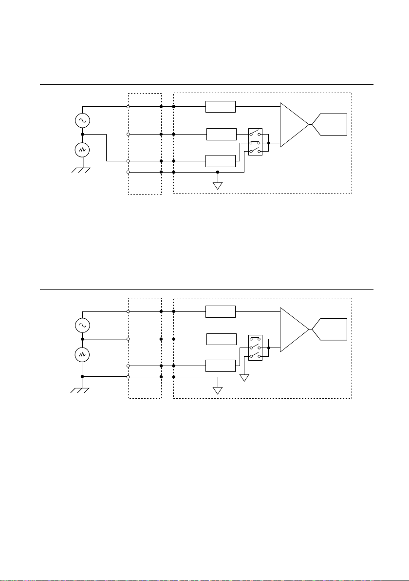
To connect non-referenced single-ended voltage signals to the NI USB-7845R OEM device,
you must connect the voltage ground signal to AI SENSE in order to keep the common-mode
voltage in the specified range, as shown in Figure 4.
Figure 4. Connecting Non-Referenced Single-Ended Signals to the NI USB-7845R
OEM Device
PGIA ADC
AI+
NI USB-7845R OEM
Connection
Accessory
AISENSE
AIGND
Vcm
V1
+
–
+
–
Overvoltage
Protection
AI– Overvoltage
Protection
Overvoltage
Protection
Connecting Differential Voltage Signals
You can connect grounded or floating differential signal sources to the NI USB-7845R OEM
device. Connect the positive voltage signal to the AI+ and the negative voltage signal to AI-.
To connect grounded differential signals to the NI USB-7845R OEM device, you must also
connect the signal reference to AI GND.
Figure 5. Connecting Grounded Differential Signals to the NI USB-7845R OEM Device
PGIA ADC
AI+
NI USB-7845R OEM
Connection
Accessory
AISENSE
AIGND
Vcm
V1
+
–
+
–
Overvoltage
Protection
AI– Overvoltage
Protection
Overvoltage
Protection
To connect floating differential signals to the NI USB-7845R OEM device, you must connect
the negative and positive signals to AI GND through 1 MΩ resistors to keep the voltage within
the common-mode voltage range. If the voltage source is outside the common-mode voltage
range, the NI USB-7845R OEM device does not read data accurately.
8| ni.com | NI USB-7845ROEM User Manual
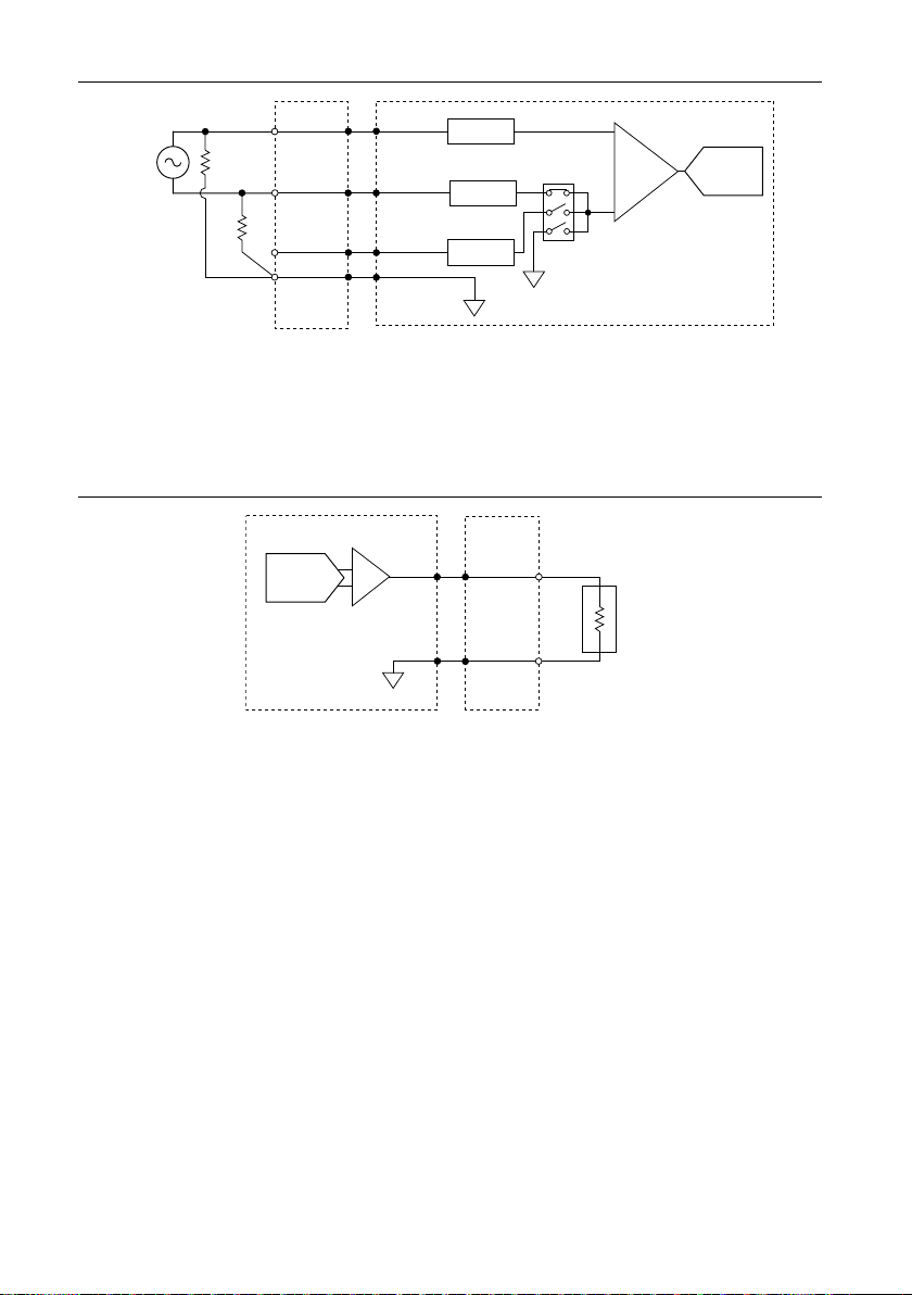
Figure 6. Connecting Floating Differential Signals to the NI USB-7845R OEM Device
PGIA ADC
AI+
NI USB-7845R OEM
Connection
Accessory
AISENSE
AIGND
V1
+
–
Overvoltage
Protection
AI– Overvoltage
Protection
Overvoltage
Protection
Analog Output
The NI USB-7845R OEM device provides connections for eight analog output channels. Each
channel has an AO pin and AOGND pin to which you can connect a load.
Figure 7. Connecting a Load
NI USB-7845R OEM
Connection
Accessory
AOGND
LOAD
AO
DAC
Digital I/O
The NI USB-7845R OEM device provides connections for 48 digital input/output (DIO)
channels. Connector 1, Connector 2, and Connector 3 contains 16 low-speed channels that can
run up to 10 MHz signal frequencies. Each connector has selectable logic levels that you can
configure as 1.2 V, 1.5 V, 1.8 V, 2.5 V, or 3.3 V. You can configure each channel as input or
output.
NI USB-7845ROEM User Manual | © National Instruments | 9

Figure 8. Connecting to the DIO Channels
NI USB-7845R OEM
Power
FPGA
Connector X/ DIO0
Connector X/ DIO1
Connector X/ DIO14
Connector X/ DIO15
1
2
1. Low-speed signal frequencies up to 10 MHz with logic levels configured as 1.2 V, 1.5 V, 1.8 V, 2.5 V, or
3.3 V. Connectors 1 and 2 share the same voltage settings.
2. LED.
The DIO channels connect to the FPGA through buffers, which have overvoltage and
undervoltage protection as well as over current protection. Refer to the NI USB-7845R OEM
Device Specifications for more information about the maximum voltage and current.
When the system powers on, the DIO channels are set as input low with pull-down resistors.
To set another power-on state, you can configure the NI USB-7845R OEM device to load a VI
when the system powers on. The VI can then set the DIO lines to any power-on state.
National Instruments recommends performing signal integrity measurements to test the effect
of signal routing with the cable and connection accessory for your application.
LEDs
If you are putting the NI USB-7845R OEM device in an enclosure, you can either seat the
optional lightpipes on the device or attach external LEDs, as described in the Attaching
External LEDs section. When the lightpipes are attached, the top row is Error, USB Ready,
and POWER LEDs, and the bottom row has the User LEDs.
The NI USB-7845R OEM device has six LEDs which reflect the device state.
Table 3. LED Descriptions
LED Description Location
POWER Solid blue when the power is on 6
USB READY Solid blue when the USB is ready 3
ERROR Solid red for error cases 2
USER1 Blue, user-defined 1
10 | ni.com | NI USB-7845ROEM User Manual
Altri manuali per NI USB-7845R
1
Indice
Altri manuali National Instruments Interfaccia USB


Manuali Interfaccia USB popolari di altre marche

PASCO
PASCO SCIENCEWORKSHOP 750 Manuale utente

Phonic
Phonic FIREFLY 302 USB Manuale utente

OHAUS
OHAUS Scout STX Series Manuale utente

Denon
Denon DN-HC4500 - DJ Mixer USB Controller Manuale utente

Lutron Electronics
Lutron Electronics Stanza SZ-CI-USB-CPN5138 Manuale utente

Paradox
Paradox PMC5-TI00 Manuale utente


