Parkside P-SA 1200 Manuale utente

SWIVEL ARM FOR
CABLE HOIST
ও
SWIVEL ARM FOR CABLE HOIST
Operation and Safety Notes
ΠΕΡΙΣΤΡΕΦΟΜΕΝΗ
ΒΑΣΗ ΠΑΛΑΓΚΟ
Υποδείξεις χειρισμού και ασφαλείας
SVINGEARM TIL HEJSEVÆRK
Brugs- og sikkerhedsanvisninger
P-SA 1200
3
Anleitung_2255411:_ 28.07.2009 15:27 Uhr Seite 1

ΠΕΡΙΣΤΡΕΦΟΜΕΝΗ
ΒΑΣΗ ΠΑΛΑΓΚΟ
ও
Before reading, unfold the page containing the illustrations and familiarise yourself with all functions of the
device.
Før du læser, vend siden med billeder frem og bliv bekendt med alle apparatets funktioner.
Πριν ξεκινήσετε την ανάγνωση, ανοίξτε τη σελίδα με τις εικόνες και εξοικειωθείτε με όλες τις
λειτουργίες της συσκευής.
GB Operation and Safety Notes Page 8
DK Brugs- og sikkerhedsanvisninger Side 13
GR Υποδείξεις χειρισμού και ασφαλείας Σελίδα 18
Anleitung_2255411:_ 28.07.2009 15:27 Uhr Seite 2

3
1
2 3
10
11
17
9
7
9
66
1
2346812
13 14 15 16 18 20
ΠΕΡΙΣΤΡΕΦΟΜΕΝΗ
ΒΑΣΗ ΠΑΛΑΓΚΟ
Anleitung_2255411:_ 28.07.2009 15:27 Uhr Seite 3

4
5
8 9
7
6
19
7
9
11
10
H=380mm
11
19
7
9
11
5
8
5
9
8
5
4
6
24
3
5
9
Anleitung_2255411:_ 28.07.2009 15:27 Uhr Seite 4

5
12
10 11
14 15
13
7
1
19
10
20
20 17
10
17
17
12 17
43
2
12 10
11
10
11
11
17
Anleitung_2255411:_ 28.07.2009 15:27 Uhr Seite 5

6
18
16 17
20 21
19
18, 15, 16
13
750 mm
max. 600 kg
18 15 16
14
13
11
17 9
10
7
Anleitung_2255411:_ 28.07.2009 15:27 Uhr Seite 6

7
22
1100 mm
max. 300 kg
Anleitung_2255411:_ 28.07.2009 15:27 Uhr Seite 7

8
GB
Table of contents: Page
1. Introduction .............................................................................9
2. Safety information...................................................................9
3. Layout and items supplied .....................................................9
4. Proper use ..............................................................................9
5. Technical data ........................................................................10
6. Before putting the machine into operation ..............................10
7. Mounting and assembly .........................................................10-11
8. Cleaning, maintenance and ordering of spare parts...............11
9. Disposal and recycling............................................................11
10. Guarantee Certificate .............................................................12
The reprinting or reproduction by any other
means, in whole or in part, of documentation
and papers accompanying products is
permitted only with the express consent of ISC
GmbH. Technical changes subject to change
Anleitung_2255411:_ 28.07.2009 15:27 Uhr Seite 8

GB
9
1. Introduction
Important!
When using equipment, a few safety
precautions must be observed to avoid injuries
and damage. Please read the complete
operating manual with due care. Keep this
manual in a safe place, so that the information
is available at all times. If you give the
equipment to any other person, give them
these operating instructions as well.
We accept no liability for damage or accidents
which arise due to non-observance of these
instructions and the safety information.
2. Safety information
Ensure that you observe the following points in
order to avoid accidents and injuries.
Do not overload your swing arm.
Do not continue to use the swing arm if it is
damaged.
Ensure that all bolts are tightly fastened
and check them frequently for your own
safety.
Ensure that the cotter pin is properly
inserted through the bore holes.
Lifting and carrying persons with the cable
winch is strictly prohibited! Additionally,
persons may not loiter underneath the
cable winch/swing arm assembly.
Persons who are not aware of these safety
precautions may not use this product.
All components must be regularly checked for
any kind of deformation or damage.
Observe the maximum permissible load
capacity (see „Technical Data“)!
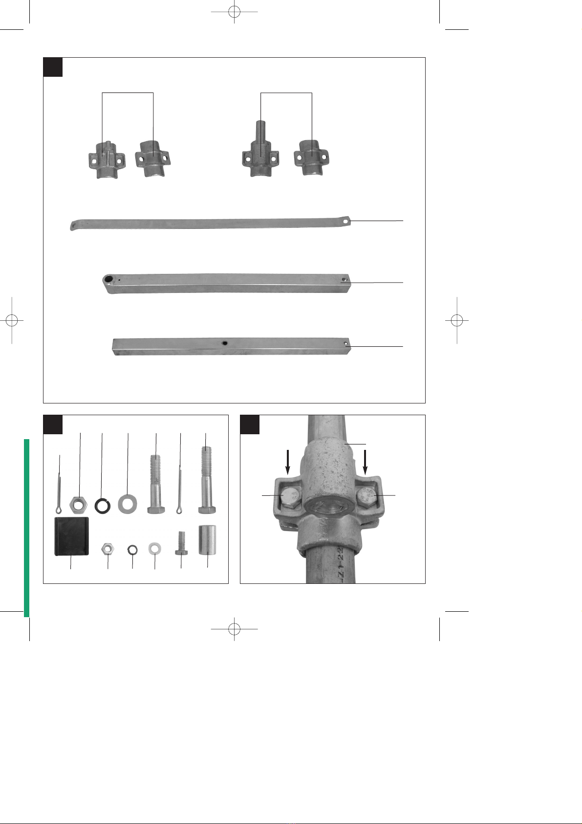
3. Layout and items supplied
(Fig. 1/2)
11. Cotter pin Ø 3 x 30
12. 5 x Hexagon nut M12
13. 5 x Spring washer Ø 12
14. 5 x Washer Ø 12
15. Hinge pin, large
16. 4 x Hexagon bolt M 12 x 60
17. Pipe collar for support arm
18. Cotter pin Ø 3 x 45
19. Pipe collar for rectangular boom
10. Support arm
11. Rectangular boom 45 x 45 x 1.8
12. Hexagon bolt M 12 x 70
13. 2 x Pads for clamping brackets
14. Hexagon nut M8
15. Spring washer Ø 8
16. Washer Ø 8
17. Extension pipe 40 x 40 x 2.5
18. Hexagon bolt M8 x 15
19. Hinge pin, small
20. Sleeve
4. Proper use
The swing arm is designed to be attached to a
cable winch. For this, the swing arm must be
mounted to a well fastened steel bar with a
diameter of 48 mm.
The machine is to be used only for its
prescribed purpose. Any other use is deemed
to be a case of misuse. The user / operator
and not the manufacturer will be liable for any
damage or injuries of any kind caused as a
result of this.
Please note that our equipment has not been
designed for use in commercial, trade or
industrial applications. Our warranty will be
voided if the machine is used in commercial,
trade or industrial businesses or for equivalent
purposes.
Anleitung_2255411:_ 28.07.2009 15:27 Uhr Seite 9

GB
10
5. Technical data
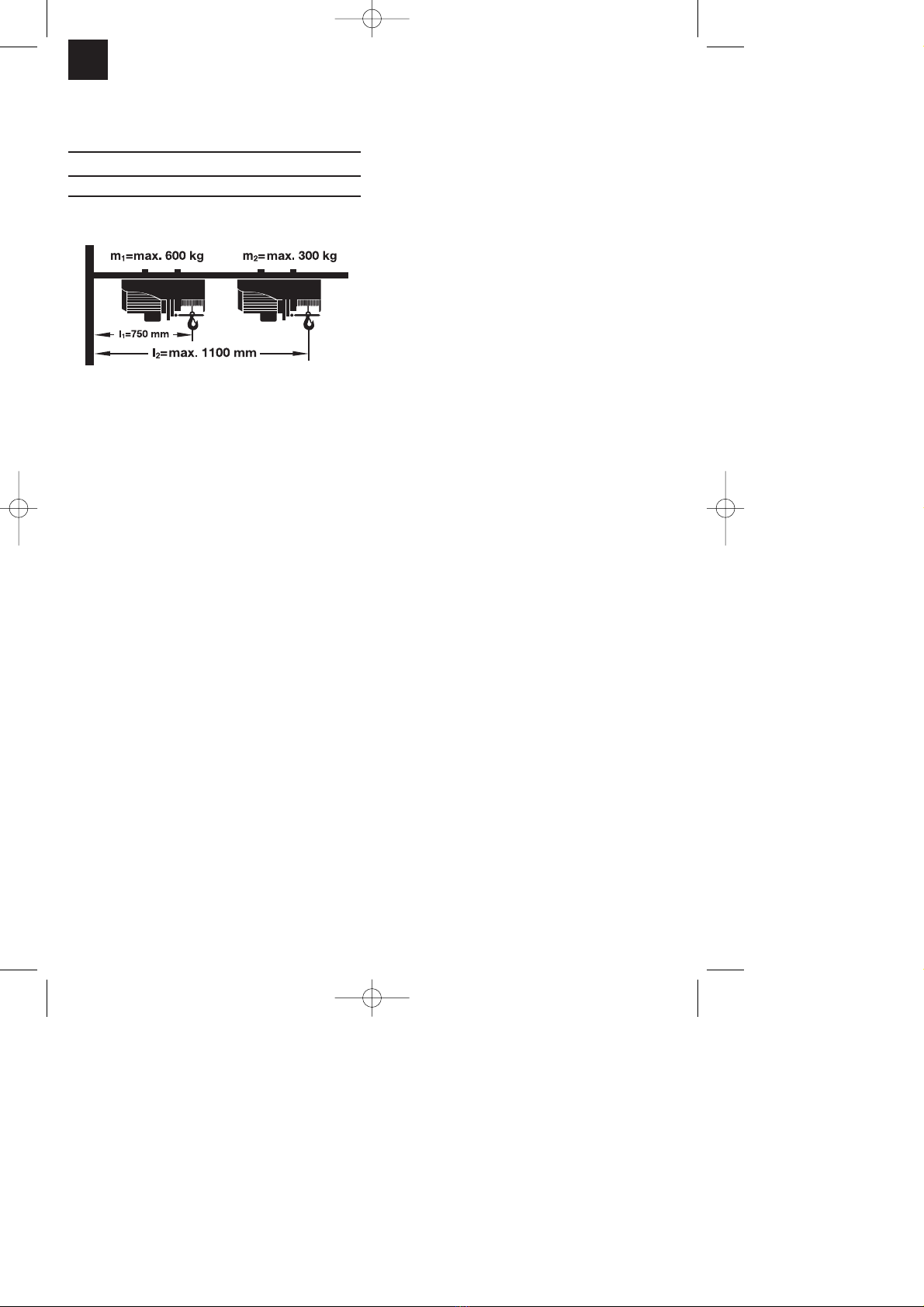
Reach l: Max. load:
l1= 750 mm m1= 600 kg
l2= 1100 mm m2= 300 kg
Swing range: max. 180°
6. Before putting the machine
into operation
The swing arm is designed to take a cable
winch.
To mount the swing arm, you need a round
steel bar with a diameter of Ø 48 mm; its
wall must be a minimum of 3 mm thick.
Ensure that the anchor points of the steel
bar are able to adequately support the
forces that will be applied to it. Consult an
authorized professional to ensure that this
is properly done.
7. Mounting and assembly
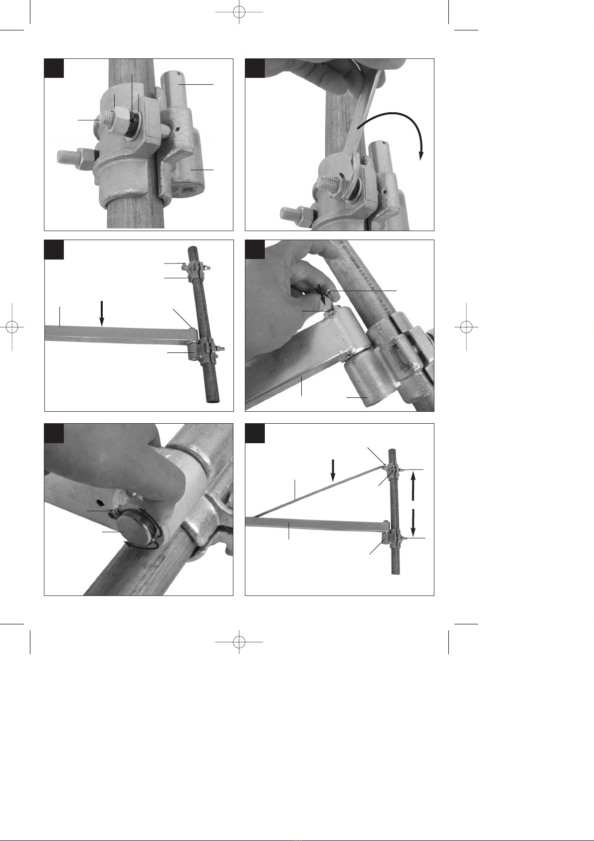
Attach pipe collar (9) (with large hinge pin
(5)) to the steel bar using the two hexagon
bolts (6), washers (4), spring washers (3)
and two hexagon nuts (2). Before you
tighten the bolts, push the pipe collar (9) to
the desired work height of the swing arm
(Fig. 3-5).
Apply lubricating grease to the hinge pin
(5).
Slide the rectangular boom (11) over the
hinge pin (5) and push the cotter pin (8)
through the hole in the hinge pin (Fig. 6-7).
Finally, bend both shanks apart from each
other so that the cotter pin (8) cannot work
its way out of the bore hole. (Fig. 8)
Now attach pipe collar (7) (with small hinge
pin (19)) to the steel bar above the
rectangular boom (11) in the same way as
you did with pipe collar (9).
Slide support arm (10) with the large bore
hole over the hinge pin of pipe collar (7).
Push the cotter pin (1) into the bore hole of
the hinge pin (19) and bend both shanks of
the cotter pin (1) apart from each other so
that the cotter pin (1) cannot work its way
out of the bore hole (Fig. 9-10).
Adjust the height of the upper pipe collar
(7) and the support arm (10) so that the
distance H between both pipe collars (7/9)
measures exactly 380 mm (Fig. 9).
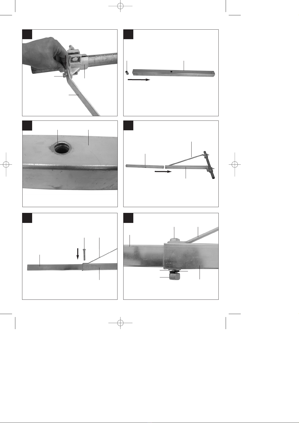
Now tighten the bolts of the pipe collars.
Tighten the bolts (6) with 70 Nm of torque.
Slide the sleeve (20) into the extension
pipe (17) until you reach the middle hole,
as shown in Figures 11 and 12. When
screwing together the square-edged boom
(11), extension pipe (17) and support arm
(10), make sure the screw (12) is inserted
into the sleeve (20).
Push the extension pipe (17) into the
rectangular boom (11) (Fig. 13).
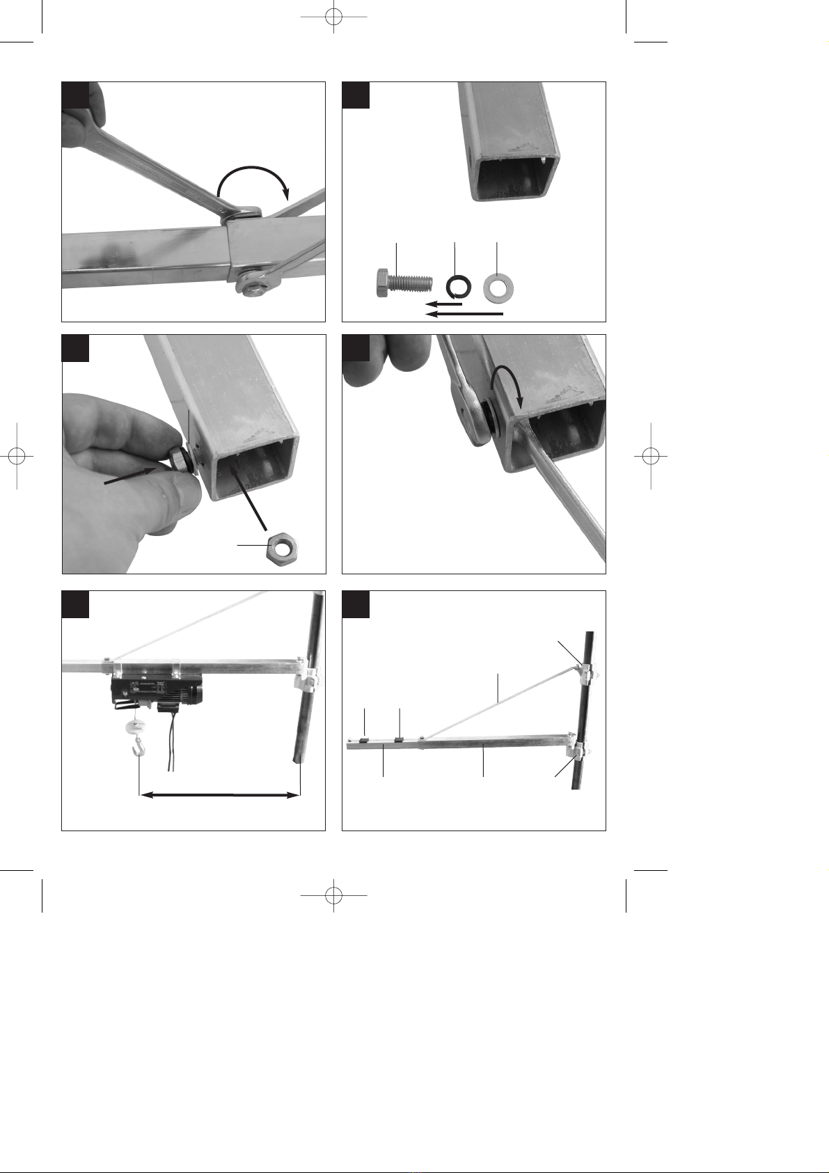
Connect the support arm (10) with the
rectangular boom (11) and the extension
pipe (17) by inserting the hexagon bolt (12)
through the overlapping bore holes, placing
a washer (4) and the spring washer (3)
over the bolt (12) and tightening with a
hexagon nut (2). (Fig. 14-16)
A bolt (18) is inserted at the end of the
extension pipe (17) to prevent the cable
winch from sliding off. (Fig. 17-19).
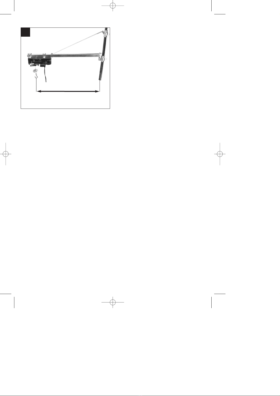
When the cable winch is pushed out to 750
mm, it may not lift any more than 600 kg
(Fig. 20).
When the cable winch is pushed out to
1100 mm, it may not lift any more than 300
kg (Fig. 22).
When mounting the cable winch to the
extension pipe (17), the pads (13) must be
pushed in under the clamping brackets in
order to ensure that the cable winch is
securely held in place (Fig. 21). After all of
Anleitung_2255411:_ 28.07.2009 15:27 Uhr Seite 10
Indice
Lingue:
Altri manuali Parkside Sistema di sollevamento
Manuali Sistema di sollevamento popolari di altre marche

Genie
Genie Z-60/34 Manuale utente

Screen Technics
Screen Technics INTERFIT Vertical Up Lift Manuale utente

Mortuary Lift
Mortuary Lift ULTIMATE 1000 Manuale utente

Custom Equipment
Custom Equipment Hy-Brid 3 Series Manuale di programmazione

Custom Equipment
Custom Equipment Hy-Brid Lifts 2 Series Manuale di programmazione

Hy-Brid Lifts
Hy-Brid Lifts HB-P3.6 Manuale di programmazione