S3x-HB-1-11
7
Table of figures
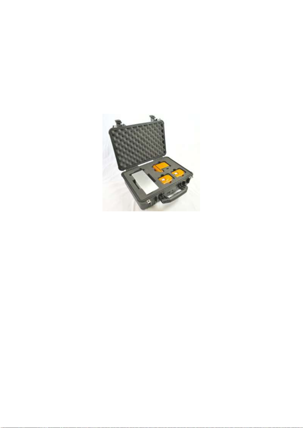
Figure 1: Remote head and receiver module in transport case..................................................................10
Figure 2: Dirty fibre interface causes performance degradation.................................................................11
Figure 3: Cleaning fluid residue cross-contaminates clean fibres ..............................................................11
Figure 4: Clean interface (i) mated with contaminated interface (ii) results in permanent damage (iii)......12
Figure 5: Power Button ...............................................................................................................................13
Figure 6: Tx1 remote head with battery disconnected................................................................................13
Figure 7: Sentinel 3 desktop chassis with two Rx1, two Rx2, and one Rx6 fitted ......................................14
Figure 8 Transmitter and receiver settings for Rx (left) and Rx+ (right) series...........................................15
Figure 9: Sensitivity or compression mode setting .....................................................................................16
Figure 10: Nineteen inch chassis dimensions ............................................................................................18
Figure 11: Desktop chassis dimensions .....................................................................................................19
Figure 12: Rear view of the interface panel................................................................................................19
Figure 13: Rx6 receiver module dimensions...............................................................................................21
Figure 14: Rx6 receiver module with deployed removal handle.................................................................21
Figure 15: Single input Tx1 remote transmit head......................................................................................23
Figure 16: Tx1 single input remote transmit head dimensions ...................................................................23
Figure 17: Tx8 eight input remote transmit head dimensions
....................................................................................................................................................................24
Figure 18: Different cable reels available (dependant on cable type and length) ......................................26
Figure 19: Rx1 module cross-site cable and connector..............................................................................26
Figure 20: Rx2 module cross-site cable and connector..............................................................................27
Figure 21: Rx6 module cross-site cable and connector..............................................................................27
Figure 22: Rx1 module patch cable and connector ....................................................................................28
Figure 23: Rx2 module patch cable and connector ....................................................................................28
Figure 24: Rx6 module patch cable and connector ....................................................................................28
Figure 25: Rx2 & Rx6 break-out solutions..................................................................................................29
Figure 26: Rx1, Rx2, and Rx6 system configurations and break-out boxes...............................................29
Figure 27: Residue free cleaning fluid ........................................................................................................30
Figure 28: Cleaning sticks for Rx1, Rx2, & Rx6 optical connectors and cables.........................................30
Figure 29: Dry fibre cleaning tools ..............................................................................................................30
Figure 30: Sentinel 3 charging shoe ...........................................................................................................31
Figure 31: Desktop charger (left) and charge shoe status LED states (right) ............................................31
Figure 32: Top-level GUI display menu ......................................................................................................33
Figure 33: Rx Module icons (left: Rx1, right: Rx2)......................................................................................33
Figure 34: Tx head Icons (left: Tx1, right: Tx8)...........................................................................................33
Figure 35: Information area in Remote Mode.............................................................................................34
Figure 36: Rx Module screen (Rx6 connected) ..........................................................................................34
Figure 37: Tx Head Screen (Tx8 connected)..............................................................................................35