20210619
1GB
INDEX
1. BURNER DESCRIPTION
One stage light oil burner.
1.1 BURNER EQUIPMENT
Flange with insulating gasket . . . .No. 1 Screw and nuts for flange to be fixed to boiler . No. 4
Screw and nuts for flange . . . . . .No. 1 Flexible oil pipes with nipples . . . . . . . . . . . . . . No. 2
7 pin plug . . . . . . . . . . . . . . . . . . .No. 1
1. BURNER DESCRIPTION . . . . . . . . . . . . 1
1.1 Burner equipment . . . . . . . . . . . . . . . . . 1
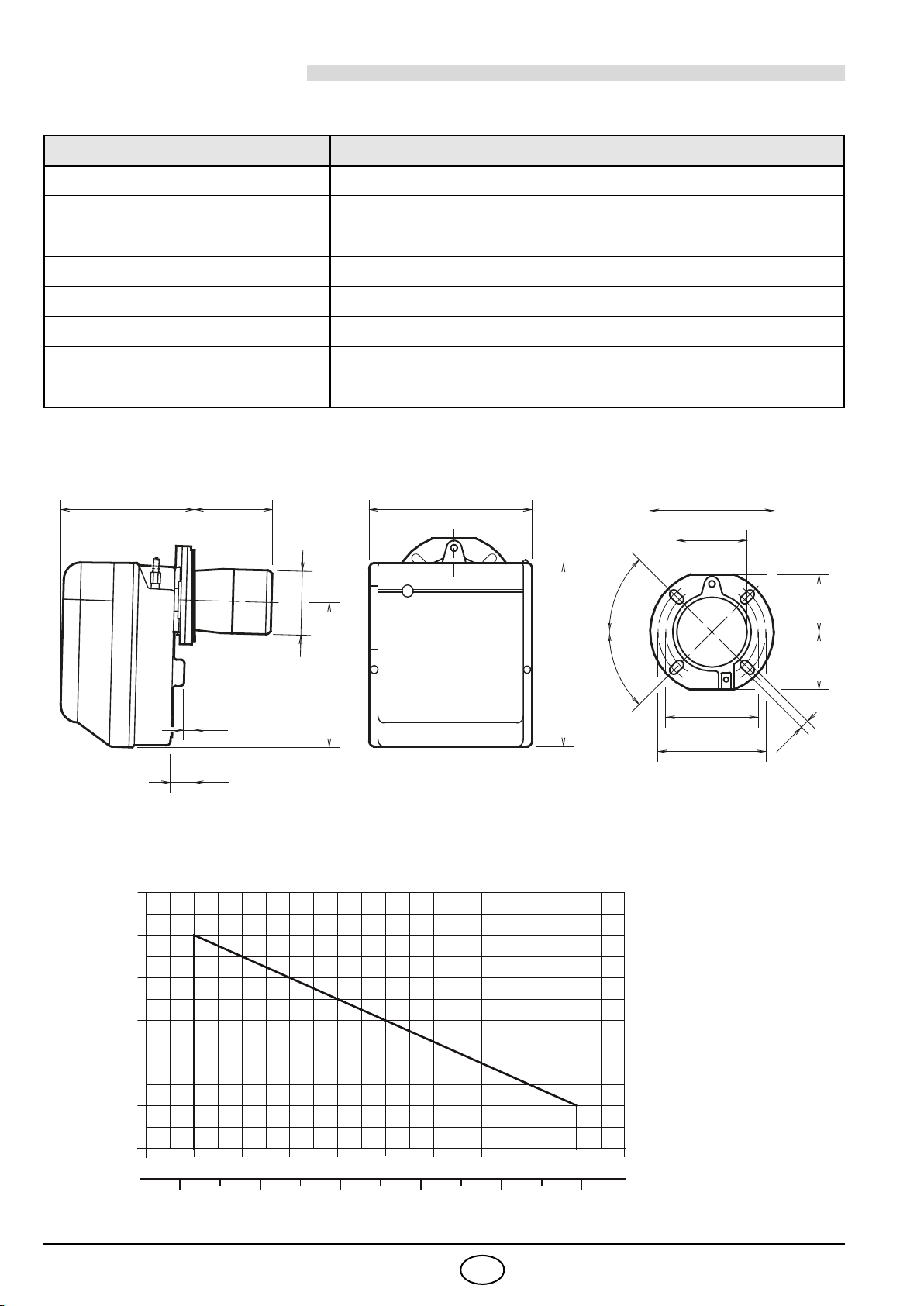
2. TECHNICAL DATA . . . . . . . . . . . . . . . . . 2
2.1 Technical data . . . . . . . . . . . . . . . . . . . . 2
2.2 Overall dimensions . . . . . . . . . . . . . . . . 2
2.3 Working field . . . . . . . . . . . . . . . . . . . . . 2
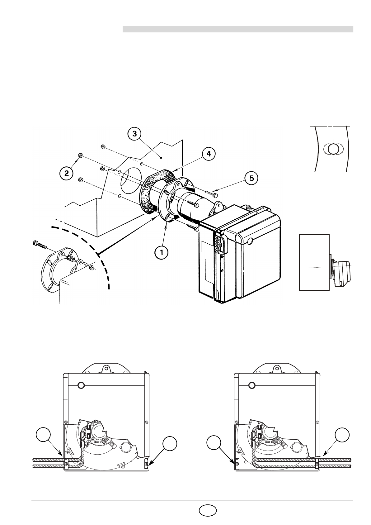
3. INSTALLATION . . . . . . . . . . . . . . . . . . . . 3
3.1 Boiler fixing . . . . . . . . . . . . . . . . . . . . . . 3
3.2 Fuel supply . . . . . . . . . . . . . . . . . . . . . . 3
3.3 Hydraulic systems . . . . . . . . . . . . . . . . . 4
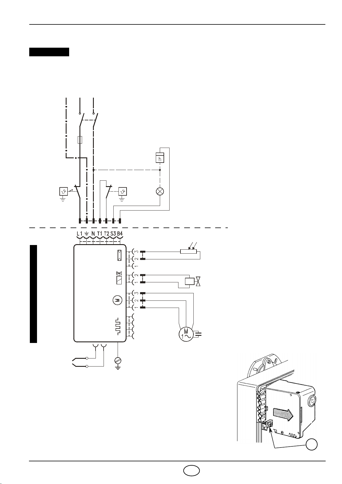
3.4 Electrical wiring . . . . . . . . . . . . . . . . . . . 5
4. WORKING . . . . . . . . . . . . . . . . . . . . . . . 6
4.1 Combustion adjustment. . . . . . . . . . . . . . 6
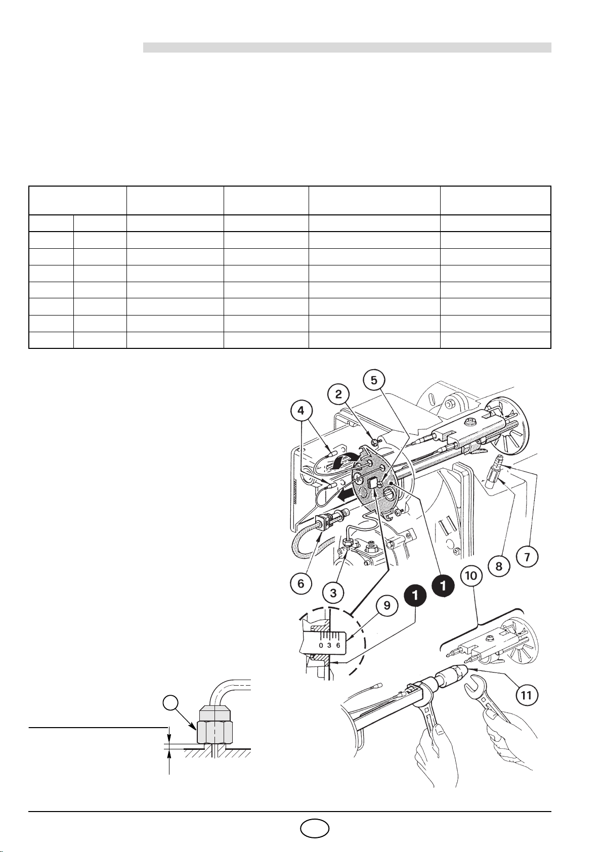
4.2 Recommended nozzles . . . . . . . . . . . . . . 6
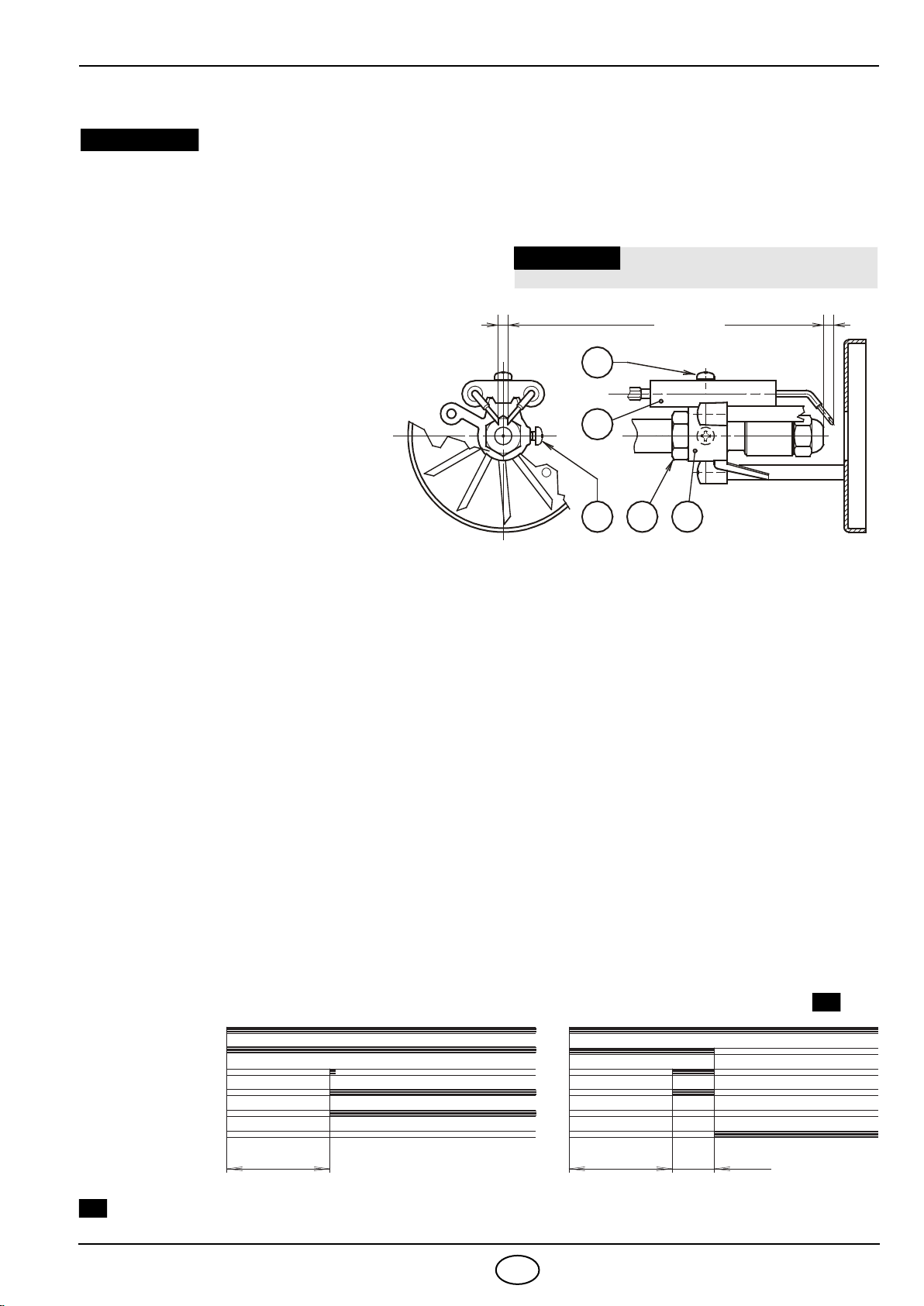
4.3 Electrodes adjustment. . . . . . . . . . . . . . . 7
4.4 Pump pressure . . . . . . . . . . . . . . . . . . . . 7
4.5 Combustion head setting. . . . . . . . . . . . . 7
4.6 Air damper adjustment . . . . . . . . . . . . . . 7
4.7 Burner start-up cycle . . . . . . . . . . . . . . . . 7
5. MAINTENANCE . . . . . . . . . . . . . . . . . . . 8
6. FAULTS / SOLUTIONS . . . . . . . . . . . . . . 9
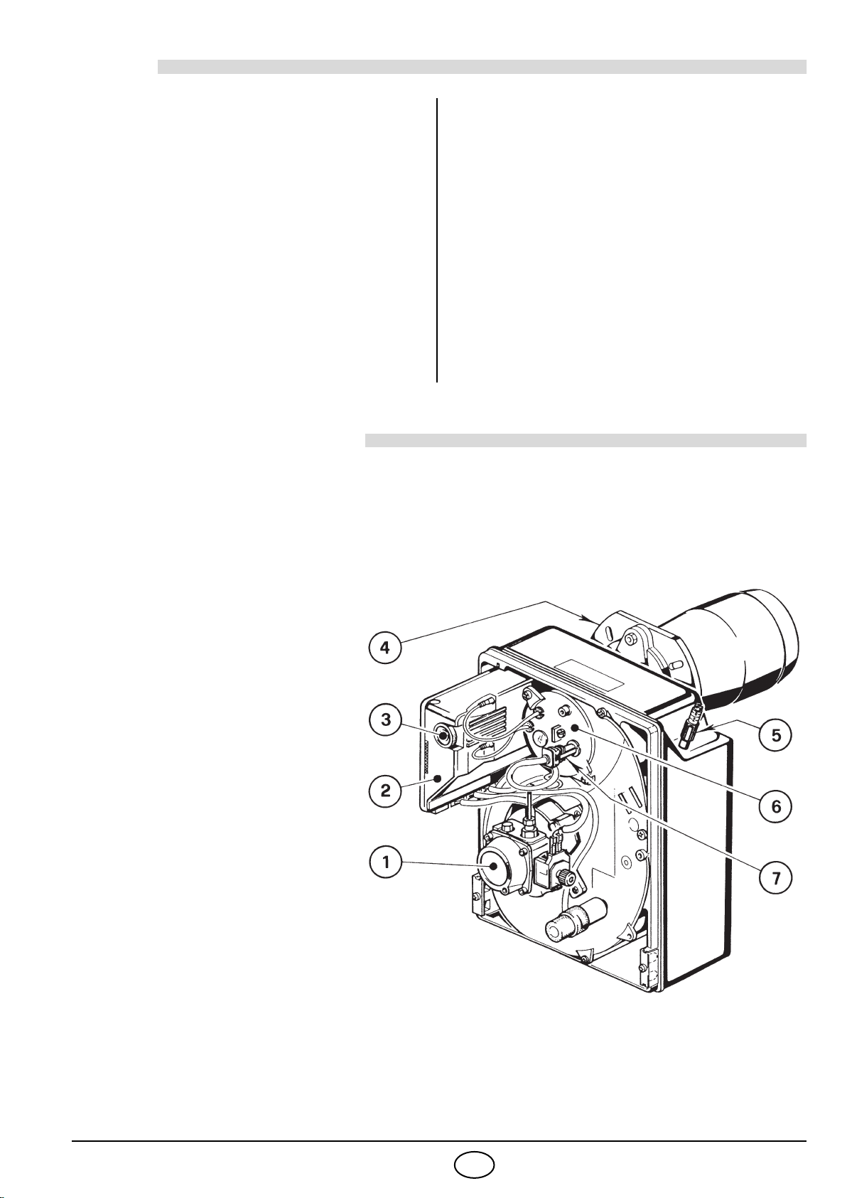
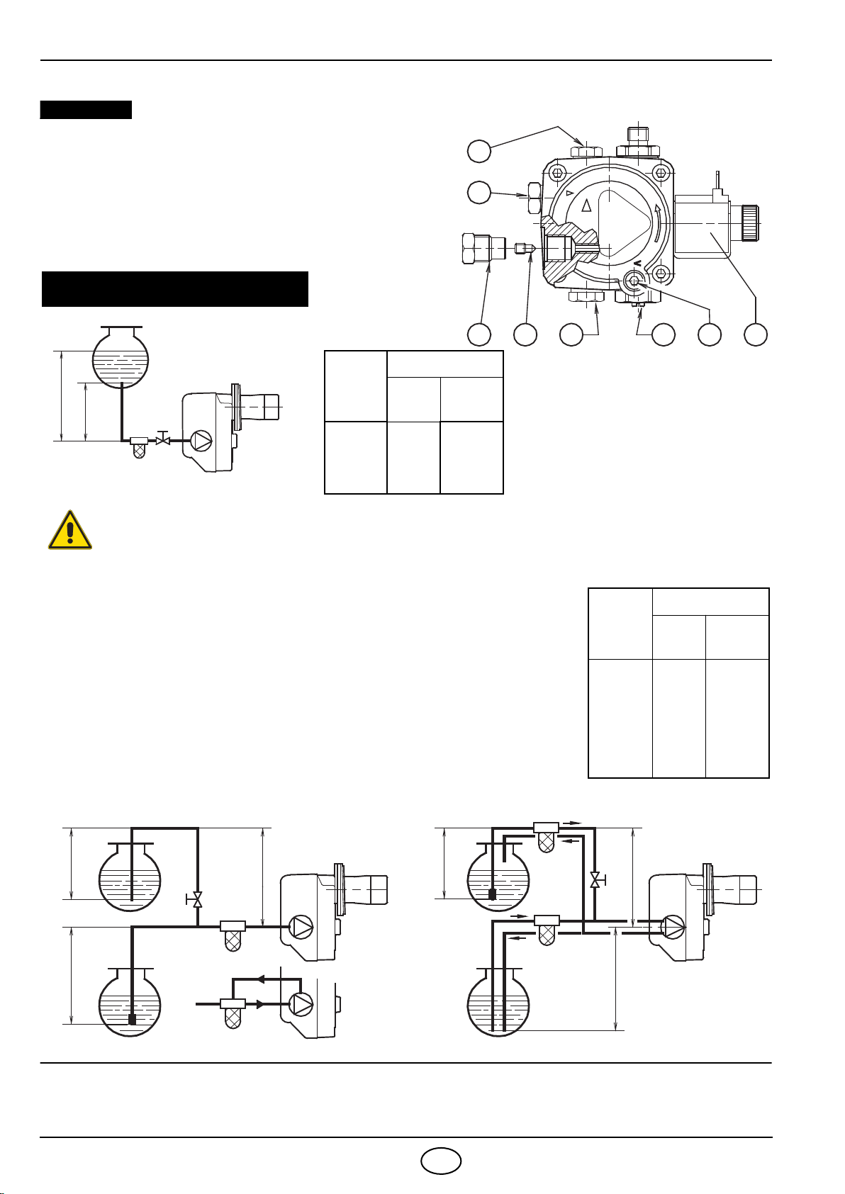
1 – Oil pump
2 – Flame control
3 – Reset button with lock-out lamp
4 – Flange with insulating gasket
5 – Air damper adjustment assembly
6 – Nozzle holder assembly
7 – Flame sensor
The burner meets protection level of IP X0D (IP 40), EN 60529.
Burner with CE marking in conformity with EEC Directives: Electromagnetic Compatibility 2004/108/EC,
Low Voltage 2006/95/EC, Machines 2006/42/EC.
Fig. 1
S7179