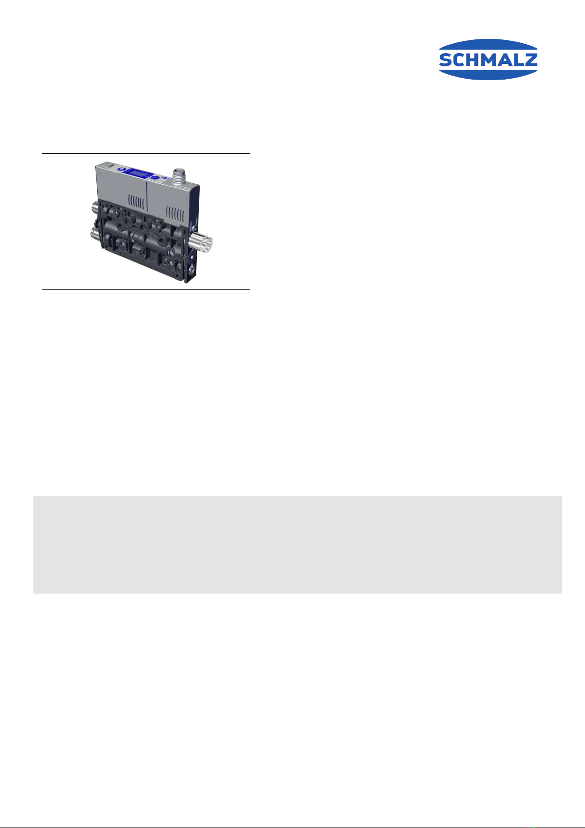
Schmalz SCPMi Manuale utente

Mini Compact Valve SCPMi,c,b EV
Operating instructions
Note
The Operating instructions were originally written in German. Store in a safe place for future reference. Subject
to technical changes without notice. No responsibility is taken for printing or other types of errors.
Published by
© J.SchmalzGmbH, 12/21
This document is protected by copyright. J.SchmalzGmbH retains the rights established thereby. Reproduction of
the contents, in full or in part, is only permitted within the limits of the legal provisions of copyright law. Any mod-
ifications to or abridgments of the document are prohibited without explicit written agreement from
J.SchmalzGmbH.
J. Schmalz GmbH · Johannes-Schmalz-Str. 1 · 72293 Glatten, Germany · T: +49 7443 2403-0
EN-US · 30.30.01.02105 · 02 · 12/21

Contents
2 / 16 EN-US · 30.30.01.02105 · 02 · 12/21
Contents
1 Important Information ...................................................................................................................................3
1.1 Note on Using this Document ............................................................................................................ 3
1.2 The technical documentation is part of the product ........................................................................ 3
1.3 Warnings in This Document................................................................................................................ 3
1.4 Other Applicable Documents ............................................................................................................. 3
1.5 Symbol.................................................................................................................................................. 3
2 Fundamental Safety Instructions...................................................................................................................4
2.1 Safety ................................................................................................................................................... 4
2.2 Intended Use........................................................................................................................................ 4
2.3 Non-Intended Use ............................................................................................................................... 4
2.4 Personnel Qualifications ..................................................................................................................... 5
2.5 Modifications to the Product.............................................................................................................. 5
3 Product Description ........................................................................................................................................5
3.1 Description of the Mini Compact Valve ............................................................................................. 5
3.1.1 Picking Up the Workpiece.......................................................................................................5
3.1.2 Depositing the Workpiece/Part (Blowing Off).......................................................................6
3.2 Operating Modes ................................................................................................................................ 6
3.3 Valve Designation ............................................................................................................................... 7
3.4 Valve Structure .................................................................................................................................... 7
4 Technical Data .................................................................................................................................................8
4.1 Performance Data ............................................................................................................................... 8
4.2 Maximum Flow Capacity..................................................................................................................... 8
4.3 Dimensions........................................................................................................................................... 9
4.4 Pneumatic Circuit Plans..................................................................................................................... 10
5 Checking the Delivery...................................................................................................................................10
6 Installation.....................................................................................................................................................10
6.1 Installation Instructions..................................................................................................................... 10
6.2 Mounting ........................................................................................................................................... 10
6.2.1 Mounting on a DIN Rail (Optional) ......................................................................................11
6.3 Pneumatic Connection ...................................................................................................................... 12
6.3.1 Connecting the Compressed Air and Vacuum .....................................................................13
6.3.2 Instructions for the Pneumatic Connection .........................................................................13
6.4 Electrical Connection......................................................................................................................... 13
7 Operation ......................................................................................................................................................14
7.1 General Preparations ........................................................................................................................ 14
8 Warranty........................................................................................................................................................14
9 Spare Parts and Accessories .........................................................................................................................14
9.1 Spare Parts ......................................................................................................................................... 14
9.2 Accessories ......................................................................................................................................... 15
10 EC Declaration of Conformity ......................................................................................................................16

1 Important Information
1.1 Note on Using this Document
J.SchmalzGmbH is generally referred to as Schmalz in these Operating instructions.
These Operating instructions contain important notes and information about the different
operating phases of the product:
• Transport, storage, start of operations and decommissioning
• Safe operation, required maintenance, rectification of any faults
The Operating instructions describe the product at the time of delivery by Schmalz.
1.2 The technical documentation is part of the product
1. For problem-free and safe operation, follow the instructions in the documents.
2. Keep the technical documentation in close proximity to the product. The documentation must be accessible
to personnel at all times.
3. Pass on the technical documentation to subsequent users.
ðFailure to follow the instructions in these Operating instructions may result in injuries!
ðSchmalz is not liable for damage or malfunctions that result from failure to heed these instructions.
If you still have questions after reading the technical documentation, contact Schmalz Service at:
www.schmalz.com/services
1.3 Warnings in This Document
Warnings warn against hazards that may occur when handling the product. The signal word indicates the level of
danger.
Signal word Meaning
WARNING Indicates a medium-risk hazard that could result in death or serious injury if
not avoided.
CAUTION Indicates a low-risk hazard that could result in minor or moderate injury if
not avoided.
NOTE Indicates a danger that leads to property damage.
1.4 Other Applicable Documents
Important:
This manual covers all of the differences arising from the use of an external vacuum supply for ejectors.
Depending on the variant, the following operating instructions must also be observed when using a mini compact
valve:
• 30.30.01.01961 for the ejector SCPMi
• 30.30.01.01963 for the ejector SCPMc
• 30.30.01.02039 for the ejector SCPMb
1.5 Symbol
This symbol indicates useful and important information.
üThis symbol represents a prerequisite that must be met prior to an operational step.
4This symbol represents an action to be performed.
ðThis symbol represents the result of an action.
Actions that consist of more than one step are numbered:
1. First action to be performed.
2. Second action to be performed.
EN-US · 30.30.01.02105 · 02 · 12/21 3 / 16

2 Fundamental Safety Instructions
2.1 Safety
The mini compact valve emits noise due to the operation of the vacuum and compressed air.
WARNING
Noise pollution due to the escape of compressed air
Hearing damage!
4Wear ear protectors.
WARNING
Uncontrolled movements of system components or falling of objects caused by incorrect ac-
tivation and switching of the Ejector while persons are in the plant (safety door opened
and actuator circuit switched off)
Serious injury
4Ensure that the valves and ejectors are enabled via the actuator voltage by installing a potential
separation between the sensor and actuator voltage.
4Wear the required personal protective equipment (PPE) when working in the danger zone.
CAUTION
Depending on the purity of the ambient air, the exhaust air can contain particles, which es-
cape from the exhaust air outlet at high speed.
Eye injuries
4Do not look into the exhaust air flow
4Wear eye protection
2.2 Intended Use
The valve is designed to monitor and control the externally supplied compressed air and vacuum media for grip-
ping and transporting objects when used in conjunction with suction cups. Depending on the design, the control
signals are transmitted directly or via appropriate communication lines.
Neutral gases are approved as evacuation media. Neutral gases include air, nitrogen and inert gases (e.g. argon,
xenon and neon).
The product is built in accordance with the latest standards of technology and is delivered in a safe operating con-
dition; however, hazards may arise during use.
The product is intended for industrial use.
Intended use includes observing the technical data and the installation and operating instructions in this manual.
2.3 Non-Intended Use
WARNING
Extraction of hazardous media, liquids or bulk material
Personal injury or damage to property!
4Do not extract harmful media such as dust, oil mists, vapors, aerosols etc.
4Do not extract aggressive gases or media such as acids, acid fumes, bases, biocides, disinfectants
or detergents.
4Do not extract liquids or bulk materials, e.g. granulates.
4 / 16 EN-US · 30.30.01.02105 · 02 · 12/21

NOTE
The vacuum connection is closed
An impermissible pressure rise in the device can lead to damage.
4Do not close the vacuum connection.
Schmalz accepts no liability for damages resulting from non-intended use of Valve. In particular, the following are
considered non-intended use:
• Use in potentially explosive atmospheres
• Use in medical applications
• Lifting people or animals
• Evacuation of objects that are in danger of imploding
2.4 Personnel Qualifications
Unqualified personnel cannot recognize dangers and are therefore exposed to higher risks!
1. Task only qualified personnel to perform the tasks described in these Operating instructions.
2. The product must be operated only by persons who have undergone appropriate training.
These Operating instructions are intended for fitters who are trained in handling the product and who can operate
and install it.
2.5 Modifications to the Product
Schmalz assumes no liability for consequences of modifications over which it has no control:
1. The product must be operated only in its original condition as delivered.
2. Use only original spare parts from Schmalz.
3. The product must be operated only in perfect condition.
3 Product Description
3.1 Description of the Mini Compact Valve
3.1.1 Picking Up the Workpiece
The valve is designed for vacuum handling of airtight parts in combination with suction systems. The vacuum is
supplied externally and the air is sucked in through the vacuum connection.
The vacuum valve is opened or closed using the suction command:
• In the NO (normally open) variant, the valve is closed when the suction signal is received.
• In the NC (normally closed) variant, the valve is opened when the suction signal is received.
A sensor integrated in types "i" and "c" detects the vacuum present. The exact vacuum level is shown on the dis-
play and, with the "i" version, can also be read from the IO-Link process data.
The diagram below shows the vacuum curve when the control function is activated:
EN-US · 30.30.01.02105 · 02 · 12/21 5 / 16

Vacuum
[mbar]
Vacuum on Time [s]
SP1
SP2
rP1
rP2
OUT=on
OUT=off
The valve has an integrated control function and automatically regulates the vacuum in suction mode:
• The electronics switch the vacuum transmission off as soon as the vacuum limit value set for switching point
SP1 is reached.
• When objects with airtight surfaces are picked up, the integrated non-return valve prevents the vacuum from
dropping quickly.
• If leaks cause the system vacuum to drop below the limit value configured for the switching point rP1, the
vacuum transmission is switched back on.
• The OUT output is set once a workpiece is picked up securely, based on the vacuum value. This enables the
further handling process.
3.1.2 Depositing the Workpiece/Part (Blowing Off)
In blow off mode, the vacuum circuit of the valve is supplied with compressed air. This ensures that the vacuum
drops quickly, allowing the workpiece to be quickly deposited.
During blow off, [-FF] is shown for versions with a display.
The valve provides three blow-off modes for selection:
• Externally controlled blow off
• Internally time-controlled blow off
• Externally time-controlled blow-off
3.2 Operating Modes
If the valve is connected to the supply voltage, it is ready for operation. This is the normal operating mode, in
which the valve is operated by the system controller.
The options for parameterizing the valve are very different depending on the version.
During the setup process, the user can:
• Control the valves manually using the manual auxiliary actuation for type "b"
• Use "Manual operation" mode for type "c"
• Use "Setup" mode (only via IO-Link) and "Manual operation" for type "i"
6 / 16 EN-US · 30.30.01.02105 · 02 · 12/21

3.3 Valve Designation
The breakdown of the item designation (e.g. SCPMc EV S09 NC M8-6 PNP ABA) is as follows:
Feature Variants
Type SCPM
Version Basic: b
Controlled: c
Intelligent: i
External vacuum supply EV
Fluid connector S09 (push-in, 4/2, 6/4 2x) G09 (M5 female, M7 female 2x)
Suction valve control NO (normally open), sucks when no voltage is applied
NC (normally closed), does not suck when no voltage is applied
Electrical connector M8 plug, 6-pole
Switch function PNP (switches to plus)
NPN (switches to minus)
Individual configuration code The 3-digit code "AAA" uniquely describes a mini compact valve.
3.4 Valve Structure
b c i
5
4
6
8
1 2 3
7
1 Type "b" control unit 2 Type "c" control unit
3 Type "i" control unit 4 Vacuum connection (marking 2)
5 Compressed air connector (marking 1) 6 External vacuum connector (marking 1A)
7 Valve screw for blow off volume flow 8 2x mounting hole
EN-US · 30.30.01.02105 · 02 · 12/21 7 / 16

4 Technical Data
4.1 Performance Data
Parameter Value with external vacuum generation
Degree of evacuation [%] Depending on the external vacuum generation
Air consumption for blow off [l/min] 10
Sound pressure level, unobstructed suction [dB(A)] 1) 66
Sound pressure level, suction [dB(A)] 55
Pressure range [bar] 4 to 6
Recommended hose diameter for compressed air hose [mm] 2) 2
Recommended hose diameter for vacuum hose [mm] 2) 4
Weight [g] 90
1) At optimal operating pressure of 4.5 bar
2) For max. length of 2m
4.2 Maximum Flow Capacity
The max. flow volume of the mini compact valve depends on:
• The rated power of the externally connected vacuum generator
• The number of valves to be supplied when used in the terminal
Flow
volume
[l/min]
Vacuum[mbar]
Required differential pressure Maximum flow volume
-600mbar 33 l/min 1)
1) If several mini compact valves are used in the terminal, the maximum flow volume per additional open suction
circuit is reduced by approx. 5%. With five mini compact valves or more, both sides of the terminal must be sup-
plied.
8 / 16 EN-US · 30.30.01.02105 · 02 · 12/21

Differential
pressure
Max. flow
rate
External
vacuum
The recommended rated power of the external vacuum generator is 125 l/min per open suction circuit or per mini
compact valve (max 8 units).
4.3 Dimensions
Illustration showing the SCPMc EV as an example
G3 L B H L1 L2 L3 X1 H1 H2
M8x1
male
thread
76.5 12 65.3 99.4 11.4 20.5 36 73.9 24.95
H3 H4 H5 H6 d1 d2 d5 d3 d4 B1
7.5 30 7.5 17.5 Depending on the particular
valve, see chapter 3.3
9 4.3 12.5
All specifications are in mm
EN-US · 30.30.01.02105 · 02 · 12/21 9 / 16

4.4 Pneumatic Circuit Plans
NC NO
5 Checking the Delivery
The scope of delivery can be found in the order confirmation. The weights and dimensions are listed in the delivery
notes.
1. Compare the entire delivery with the supplied delivery notes to make sure nothing is missing.
2. Damage caused by defective packaging or occurring in transit must be reported immediately to the carrier
and J.SchmalzGmbH.
6 Installation
6.1 Installation Instructions
CAUTION
Improper installation or maintenance
Personal injury or damage to property
4During installation and maintenance, make sure that the product is disconnected and depressur-
ized and that it cannot be switched on again without authorization.
For safe installation, the following instructions must be observed:
• Use only the connectors, mounting holes and attachment materials that have been provided.
• Mounting and removal must be performed only when the device is unpressurized and disconnected from the
mains.
• Pneumatic and electrical line connections must be securely connected and attached to the product.
6.2 Mounting
The valve may be installed in any position.
The valve is usually mounted using the holes on the side. Alternatively, it can be mounted using a DIN rail or a
mounting bracket Accessories:
10 / 16 EN-US · 30.30.01.02105 · 02 · 12/21
Altri manuali per SCPMi
1
Questo manuale è adatto per i seguenti modelli
2
Indice
Altri manuali Schmalz Unità di controllo
Manuali Unità di controllo popolari di altre marche

Festo
Festo Compact Performance CP-FB6-E Manuale elenco delle parti

Elo TouchSystems
Elo TouchSystems DMS-SA19P-EXTME Manuale utente

JS Automation
JS Automation MPC3034A Manuale utente

JAUDT
JAUDT SW GII 6406 Series Guida rapida

Spektrum
Spektrum Air Module System Manuale utente

BOC Edwards
BOC Edwards Q Series Manuale utente