Semtech EB-GS3471-00 Manuale utente

EB-GS3471-00
Evaluation Board User Guide
1 of 22
Semtech
Proprietary & Confidential
GS3471
Evaluation Board User Guide Rev.3
PDS-061243 March 2018
www.semtech.com

GS3471
Evaluation Board User Guide Rev.3
PDS-061243 March 2018
2 of 22
Semtech
Proprietary & Confidential
www.semtech.com
Revision History
Contents
1. EB-GS3471-00 User Guide ............................................................................................................................5
1.1 Power (J5 or J13) .................................................................................................................................5
1.2 SDI Input (J6 and J7) ..........................................................................................................................6
1.3 Switch Settings (SW1 and SW2) ....................................................................................................6
1.3.1 GS3471 Switch Settings (SW1)...........................................................................................6
1.3.2 GS2988 Switch Settings (SW2)...........................................................................................7
1.4 3G-SDI Loop Through (J10) .............................................................................................................8
1.5 Video Header (J1) ...............................................................................................................................8
1.6 Audio Header (H1, J4 and J12) .......................................................................................................9
1.6.1 Audio Header (H1) .................................................................................................................9
1.6.2 AES Model — RCA Connectors (J4 and J12) .............................................................. 10
1.7 JTAG Header ...................................................................................................................................... 11
1.8 Status LED’s ....................................................................................................................................... 11
1.9 Modes of Operation ........................................................................................................................ 12
2. EB-GS3471-00 Schematics......................................................................................................................... 13
3. EB-GS3471-00 Board Layout..................................................................................................................... 17
4. EB-GS3471-00 Bill of Materials (BOM).................................................................................................... 19
Version ECO PCN Date Changes and/or Modifications
3 041088 — March 2018 Updated Section 1.1.
2 038786 — September 2017
Digital and analog ground pin names updated to CORE_GND
and A_GND respectively.
Updates to Pin A1, A2, F1, G1 in Figure 2-3.
1 034214 — November 2016 Pin A7 changed to RSVD in Figure 2-3.
0 030575 — May 2016 New document.

GS3471
Evaluation Board User Guide Rev.3
PDS-061243 March 2018
3 of 22
Semtech
Proprietary & Confidential
www.semtech.com
Overview
Together with the EB-GS3471-00 Evaluation Board, this document serves as a guide for
evaluating the GS3471. The GS3471 is a Semtech 3Gb/s, HD, SD SDI Receiver. For more
information on the GS3471, please refer to the Product Data Sheet (PDS-060500). This
document is partitioned into the following sections:
•EB-GS3471-00 User Guide
•EB-GS3471-00 Schematics
•EB-GS3471-00 Board Layout
•EB-GS3471-00 Bill of Materials (BOM)
Figure A below shows a block diagram of the features and the functions of the
EB-GS3471-00.
The board includes power supplies, USB control interface, two 3G-SDI inputs, one
GS3140 equalizer, a 3G-SDI loop-through output, a GS2988 multi-rate cable driver, a
GS3471 Receiver, a parallel video output connector, an audio output with four RCA for
AES audio, a 27MHz crystal, DIP switches, and a few status indication LEDs.
The GS3471 will automatically detect the input signal (J6 and J7) as SD-SDI, HD-SDI, or
3G-SDI. The deserialized video is available on the parallel output connector (J1). The
extracted audio is available as serial audio or AES on audio headers (J4 and J12). A serial
digital loop-through output (J10) is also available.
The EB-GS3471-00 also provides a JTAG interface used for boundary scan and a USB
interface to control the GS3471 and the GS3140 through the GSPI ports on the devices.
Kit Contents
•Semtech EB-GS3471-00 Evaluation Board
•Semtech AB-GS3470 Adaptor Board
•Micro USB Cable (for GUI communication)
•DC Power Terminal

GS3471
Evaluation Board User Guide Rev.3
PDS-061243 March 2018
4 of 22
Semtech
Proprietary & Confidential
www.semtech.com
Figure A: Block Diagram
GS3471
De-serializer
FTDI
HEADER
RCA x2
TERM0
TERM1
AUDIO
ACLK
WCLK
AMCLK
GSPI
DOUT[19:0]
PCLK, HVF
JTAG SWITCH
GS3140
GS2988
AUDIO
RESET PB
LEDs
STAT3
STAT4
STAT5
LF
DDO
SDI
DDI
RCA x2
Power
USB
3G-SDI IN 1
3G-SDI IN 0
3G-SDI LOOP
THROUGH

GS3471
Evaluation Board User Guide Rev.3
PDS-061243 March 2018
5 of 22
Semtech
Proprietary & Confidential
www.semtech.com
1. EB-GS3471-00 User Guide
Figure 1-1: GS3471 Evaluation Board (EB-GS3471-00)
1.1 Power (J5 or J13)
The EB-GS3471-00 board is powered by a +5V supply through a Micro-B USB connector
(J5) or through the auxiliary power connector (J13). Not all USB ports are capable of
supplying enough current to power the board. In this case, use the external +5V
auxiliary power connector (J13) with the included DC power terminal. Connect the
auxiliary power supply before connecting the USB.
LED D10 is used to indicate if there is voltage present on the +5V input.
LED D7 is used to indicate if the voltage connected to J13 has been reversed.
Status LEDs
3G-SDI IN 0 (J6)
3G-SDI IN 1 (J7)
DIP Switch (SW2)
3G SDI Loop
Through (J10)
Serial Audio
Output (H1)
RCA Output (J4 and J12)
Auxiliary Power Connector (J13)
Micro-B USB (J5)
Reset Button (SW3)
DIP Switch (SW1)
Parallel Video
Output (J1)

GS3471
Evaluation Board User Guide Rev.3
PDS-061243 March 2018
6 of 22
Semtech
Proprietary & Confidential
www.semtech.com
1.2 SDI Input (J6 and J7)
The EB-GS3471-00 includes two 3G-SDI inputs DC-coupled to the GS3471. The applied
video stream will first pass through Semtech's GS3140 Cable Equalizer (PDS-060939)
before entering the DDI input pin of the GS3471. The pin J6 provides a DC path to the
GS3471 through the GS3140, while the pin J7 provides a direct AC path to the GS3471.
1.3 Switch Settings (SW1 and SW2)
1.3.1 GS3471 Switch Settings (SW1)
Figure 1-2 shows the switch settings for SW1 which control the static configuration
input of the GS3471.
Figure 1-2: GS3471 Switch Configuration
Table 1-1: SW1 Switch Settings
Switch Pin Description
SW1.1 JTAG TRST
When HIGH, the GS3471 JTAG interface is in
operational mode.
When LOW, the GS3471 JTAG interface is held
in reset.
SW1.2 JTAG interface
enable
When HIGH, the GS3471 JTAG interface is in
operational mode.
When LOW, the GS3471 JTAG interface is
disabled.
SW1.3 BIT20/BIT10
Used to select the video output bus width.
When HIGH, 20-bit bus width.
When LOW, 10-bit bus width.
LOGIC “HIGH”
LOGIC “LOW”
SW1.5
SW1.4
SW1.3
SW1.2
SW1.1
SW1.5
SW1.4
SW1.3
SW1.2
SW1.1
LOGIC HIGH
LOGIC LOW

GS3471
Evaluation Board User Guide Rev.3
PDS-061243 March 2018
7 of 22
Semtech
Proprietary & Confidential
www.semtech.com
1.3.2 GS2988 Switch Settings (SW2)
Figure 1-3 shows the switch settings for SW2 which controls the static configuration
input pins of the GS2988.
Figure 1-3: GS2988 Switch Configuration
SW1.4 PWR_DWN
When HIGH, places the GS3471 in low-power
mode.
When LOW, normal operation mode occurs.
Note: This switch should be in the HIGH
position to allow the GUI to control lower
power modes.
SW1.5 Audio_EN/DIS When HIGH, audio extraction is enabled.
When LOW, audio extraction is disabled.
Table 1-1: SW1 Switch Settings (Continued)
Switch Pin Description
Table 1-2: SW2 Switch Settings
Switch Pin Description
SW1.1 EQ_EN When HIGH, trace-equalization is turned off.
When LOW, trace-equalization is turned on.
SW1.2 DISN
Sets the GS2988 into low power mode.
When HIGH, the GS2988 will be in normal
operation mode.
When LOW, the entire device is powered
down.
SW1.3 SD_HDN
When HIGH, the serial data output will meet
the SMPTE 259M rise/fall time specification.
When LOW, the serial output will meet the
SMPTE 292M and SMPTE 424M rise/fall time
specification.
LOGIC “HIGH”
LOGIC “LOW”
SW1.3
SW1.2
SW1.1
SW1.3
SW1.2
SW1.1
LOGIC HIGH
LOGIC LOW

GS3471
Evaluation Board User Guide Rev.3
PDS-061243 March 2018
8 of 22
Semtech
Proprietary & Confidential
www.semtech.com
1.4 3G-SDI Loop Through (J10)
The output connector J10 is used for the 3G-SDI loop though output. The output for the
EB-GS3471-00 evaluation board is capable of the following standards:
•SMPTE 424M
•SMPTE 292M
•SMPTE 259M
The EB-GS3471-00 evaluation board supports DVB-ASI at 270Mb/s and data rates from
270Mb/s to 2.97Gb/s. The output is configured for a single ended coaxial cable
terminated with a BNC connection.
1.5 Video Header (J1)
Parallel video data with the PCLK and timing signals H, V, and F are available on a 60-pin
connector (J1). Using AB-GS3471-00 will allow the EB-GS3471-00 to interface to legacy
evaluation boards.
Figure 1-4: Video Header
Table 1-3: Pin Out Video Header
Pin Number Net Name
J1.1, J1.3, J1.5, J1.7, J1.9,
J1.11, J1.13, J1.15, J1.17,
J1.19, J1.21, J1.23, J1.25,
J1.27, J1.29, J1.31, J1.33,
J1.35, J1.37, J1.39, J1.41,
J1.43, J1.45, J1.47, J1.49,
J1.51, J1.53, J1.55
CORE_GND
J1.2 DATA[0]
J1.4 DATA[1]
J1.6 DATA[2]
J1.8 DATA[3]
J1.10 DATA[4]
J1.12 DATA[5]
J1.14 DATA[6]
Pin 1
Pin 2 Pin 60
Pin 59
Face view
Face View
Pin 2
Pin 1
Pin 60
Pin 59

GS3471
Evaluation Board User Guide Rev.3
PDS-061243 March 2018
9 of 22
Semtech
Proprietary & Confidential
www.semtech.com
1.6 Audio Header (H1, J4 and J12)
Audio Outputs (H1 and RCA connectors J4 and J12), are provided to monitor audio in
raw form (H1) and AES mode (J4 and J12).
1.6.1 Audio Header (H1)
This connector provides extracted 8-channel audio in conjunction with AMCLK, ACLK,
and WCLK.
J1.16 DATA[7]
J1.18 DATA[8]
J1.20 DATA[9]
J1.22 DATA[10]
J1.24 DATA[11]
J1.26 DATA[12]
J1.28 DATA[13]
J1.30 DATA[14]
J1.32 DATA[15]
J1.34 DATA[16]
J1.36 DATA[17]
J1.38 DATA[18]
J1.40 DATA[19]
J1.42, J1.46 N/C
J1.48 STAT0_HSYNC
J1.50 STAT1_HSYNC
J1.52 STAT2_DE
J1.54 GSPI_CS_N
J1.56 GSPI_SCLK
J1.57 USB_5V_D
J1.58 GSPI_SDIN_EXT
J1.59 USB_GPIO0
J1.60 GSPI_SDOUT_EXT
Table 1-3: Pin Out Video Header (Continued)
Pin Number Net Name

GS3471
Evaluation Board User Guide Rev.3
PDS-061243 March 2018
10 of 22
Semtech
Proprietary & Confidential
www.semtech.com
Figure 1-5: Audio Header (H1)
This pin-out takes precedence over the silk-screening on the EB-GS3471-00.
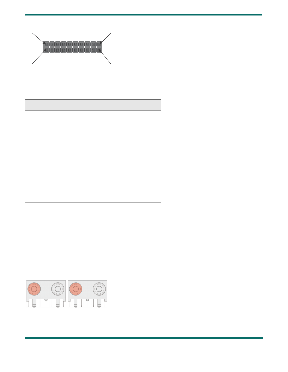
1.6.2 AES Model — RCA Connectors (J4 and J12)
For AES mode, AES-encoded CMOS-level signals are distributed through line drivers,
and supplied to two RCA connectors (J4 and J12).
Figure 1-6: RCA Connectors (J4 and J12)
Table 1-4: Pin-Out Audio Header
Pin Number Net Name
H1.1,
H1.3,
H1.13,
H1.15
AOUT_7_8,
AOUT_5_6,
AOUT_3_4,
AOUT_1_2
H1.2, H1.4, H1.6, H1.8, H1.9, H1.10,
H1.12, H1.14, H1.16, H1.18 CORE_GND
H1.5 ACLK
H1.7 AMCLK
H1.11 WCLK
H1.17 +3.3V
H1.19 IO_VDD
H1.20 N/C
Pin 20
Pin 19 Pin 1
Pin 2
Face view
Face View
Pin 19
Pin 20
Pin 1
Pin 2
J4 J12
AOUT 1-2
AOUT 3-4
AOUT 5-6
AOUT 7.8
Face view
Face View
J12J4
AOUT_1_2
AOUT_3_4
AOUT_5_6
AOUT_7_8
Indice
Altri manuali Semtech Scheda madre

Semtech
Semtech SX1211-11SKA Manuale utente

Semtech
Semtech SC21150 Manuale utente

Semtech
Semtech TSWITX-12V-EVM Manuale utente

Semtech
Semtech SC120 Manuale utente

Semtech
Semtech SX8650 Manuale utente

Semtech
Semtech SC202A EVB Manuale utente

Semtech
Semtech SX1211SK915 Manuale utente

Semtech
Semtech SX9306 Manuale utente

Semtech
Semtech GS3440 Manuale utente

Semtech
Semtech Lora Mote Manuale utente
Manuali Scheda madre popolari di altre marche

Telit Wireless Solutions
Telit Wireless Solutions SL869-3DR Manuale utente

Gigabyte
Gigabyte GA-9IVDT Manuale utente

Texas Instruments
Texas Instruments ADS8372EVM Manuale utente

Commell
Commell MS-C73 Manuale utente

IBT Technologies
IBT Technologies MB860 Manuale utente

Nvidia
Nvidia TEGRA DG-04927-001_V01 Manuale utente