Sensia CLIF MOCK CD-20A Manuale utente

CLIF MOCK™
CD-20A Sample Probe Controller
User Manual
Manual No. 2350753-01, Rev. 02
Class I Groups C and D
Hazardous Locations

Important Safety Information
Symbols and Terms Used in this Manual
!WARNING: This symbol identies information about practices or circumstances that can lead to per-
sonal injury or death, property damage, or economic loss.
CAUTION: Indicates actions or procedures which if not performed correctly may lead to personal
injury or incorrect function of the instrument or connected equipment.
Important: Indicates actions or procedures which may affect instrument operation or may lead to an
instrument response which is not planned.
Technical Support Contact Information
Global headquarters:
Sensia LLC
200 Westlake Park Blvd
Houston, TX 77079
Clif Mock is a trademark of Sensia
All Rights Reserved.
Printed in the United States of America.
Manual No. 2350753-01, Rev. 02
September 2013

iii
CD-20A Sample Probe Controller
Contents
Important Safety Information ...............................................................................................................................ii
Section 1—Overview .......................................................................................................................................... 5
How It Works ................................................................................................................................................ 6
Pulse Input Scaling ...................................................................................................................................... 6
Table 1.1—Pulse Input Switch Setting Examples ........................................................................................ 6
Repeat Time Scaling .................................................................................................................................... 7
Table 1.2—Repeat Time Switch Setting Examples ...................................................................................... 7
Hazardous Location Safety Compliance ...................................................................................................... 7
Table 1.3—CD-20A Specications ............................................................................................................... 7
Section 2—Installation and Wiring...................................................................................................................... 8
Section 3—Maintenance .................................................................................................................................... 9
Operational Test ........................................................................................................................................... 9
Repeat Mode (Time-Proportional) Check-Out ........................................................................................... 10
External Pulse Mode (Flow-Proportional) Check-Out ................................................................................ 10
Sample Probe and CD-20A Check-Out ..................................................................................................... 10
Motor Control Assembly ..............................................................................................................................11
Table 3.1—Troubleshooting Tips for 12VDC/24VDC Controllers .............................................................. 12
Table 3.2—Troubleshooting Tips for 115VAC/230VAC Controllers ............................................................ 13
Factory Repairs .......................................................................................................................................... 14

iv
Table of Contents CD-20A Sample Probe Controller
5
CD-20A Sample Probe Controller
Section 1—Overview
The CD-20A Sample Probe Controller is engineered for use with the True-Cut C-Series sample probe. It
provides both pulse input (ow proportional) and repeat (time proportional) control of the sample probe.
When a “start” pulse is received, the probe is rotated to capture and discharge an isokinetic sample. When
installed in a horizontal line, the probe is stopped in the closed position, while on a vertical line the probe is
stopped in the open position.
The C21 probe collects one 1.5 cc sample per 360-degree rotation.
The C22 probe collects two 1.5 cc samples per 360-degree rotation.
An explosion-proof housing encloses the complete assembly, and two ¾-in. NPT holes allow connection of
the line power and input pulse (for ow-proportional sampling). A ½-in. breather plug and a ½-in. conduit
plug are installed on opposite sides of the enclosure.
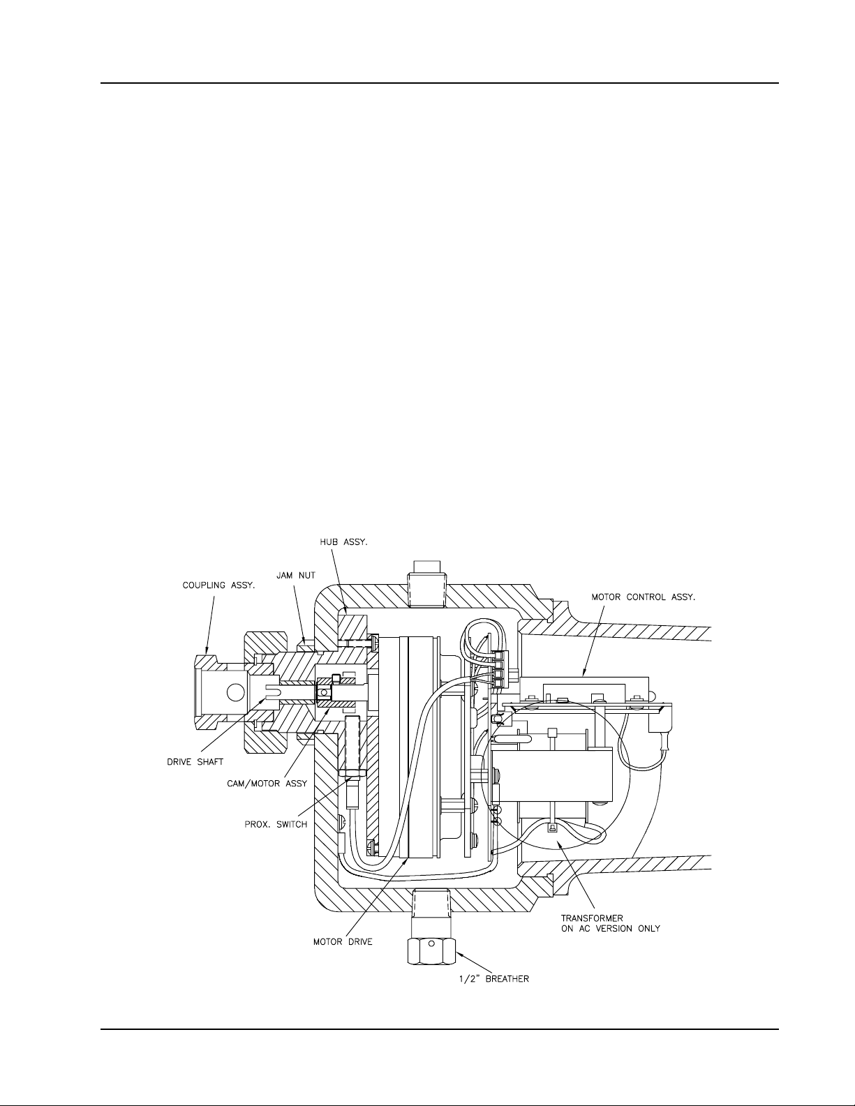
A coupling, jam nut, and hub allow the assembly to be mounted directly to the C-Series sample probe. No
brackets or supports are required; however, they are recommended for piping with signicant vibration.
The CD-20A controller consists of the following:
• a motor control assembly (12VDC, 24VDC, 115VAC, or 230VAC)
• a DC gear motor with a gear ratio of 150:1
• a cam with two high points mounted on the gear motor output shaft
• a proximity switch
Figure 1.1—CD-20A controller components

6
CD-20A Sample Probe Controller
The motor control assembly (Figure 1.2) consists of a control card and power board mounted to a ring, which
in turn, is mounted to the back of the CD-20A gear motor. All eld connections are to terminal block 1TB on
the control card. The motor and proximity switch connections are made at the factory to terminal block 2TB
on the power board.
CD20 Power Board
(2TB)
CD20 Control Card
(1TB)
Figure 1.2—CD-20A motor control assembly
How It Works
When an input pulse from either the repeat-mode timer or an external pulse source is received, a command
is output to rotate the motor. Armature feedback controls the speed of the motor at about 12 rpm and current
feedback limits motor current to 3 amperes.
Pulse Input Scaling
The four pulse scaling switches labeled X1000, X100, X10, and X1 allow selection of the desired number of
ow pulses per sample. Some switch setting examples are shown below.
Table 1.1—Pulse Input Switch Setting Examples
Switch Settings Pulses Per Sample
X1000 X100 X10 X1
0001 1
0 0 1 0 10
0 1 0 0 100
1000 1,000
1234 1,234
9999 9,999
7
CD-20A Sample Probe Controller
Repeat Time Scaling
The repeat mode utilizes a 1-Hz clock signal in lieu of the external ow proportional pulses to pace the
sample probe. The X1000, X100, X10, and X1 switches allow direct repeat time settings in seconds (see
below).
Table 1.2—Repeat Time Switch Setting Examples
Switch Settings Time Between
Samples (seconds)
X1000 X100 X10 X1
0003 3
0 0 1 0 10
0 1 0 0 100
1000 1,000
1234 1,234
9999 9,999
The repeat mode (time-proportional sampling) can be used as a test mode and a backup for the external input
pulse mode (ow-proportional sampling).
The proximity switch input amplier provides the signal to stop the motor. Two LEDs installed on the
controller card allow the user to test the controller’s operation. The I-LIMIT LED is on when the drive is in
current limit, which is normal during acceleration.The PROX (“Hold”) LED is on when the motor is stopped.
Field wiring instructions are provided in Section 2—Installation and Wiring, page 8. A signal verifying the
180-degree rotation of the motor can be transmitted to a control room if desired.
Hazardous Location Safety Compliance
Assemblies designed for 24VDC, 115VAC and 230VAC input power are UL-listed in the US and Canada for
Class I Groups C and D Hazardous Locations.
A 12VDC controller is available without the UL listing.
Table 1.3—CD-20A Specications
12/24 VDC 115/230 VAC
Temperature -40ºC to 55ºC -40ºC to 55ºC
Voltage 24VDC @2A max 115 / 230 VAC @ 1A max
Pulse Input 12VDC 12VDC
Transistor Output 12VDC max @ 100mA max 12VDC max @ 100mA max
Current Draw (Controller)
Stop Mode 30 mA 60 mA
Running Mode 0.5 Amp 150 mA
Peak Motor (Turn On) Current 1 Amp 300 mA
Current Draw (Motor)
Motor (Turn On) Current 320 mA 850 mA

8
CD-20A Sample Probe Controller
Section 2—Installation and Wiring
!WARNING: This module is designed for connection to hazardous electric voltages. Ignoring
this warning can result in severe personal injury or mechanical damage. This product must
be reliably earthed and installed by qualied personnel in accordance with the prevailing local
electrical wiring regulations and safety standards.
The CD-20A controller mounts directly to the C-Series sample probe via the DC-2 coupling (Figure 2.1).
The DC-2 coupling should be hand-tightened to ensure that the internal retaining ring is not pushed out of its
groove. If the DC-2 coupling is over-tightened at the CD-20A hub, the motor shaft will not engage the DC-1
coupling on the probe.
Figure 2.1—DC-2 coupling
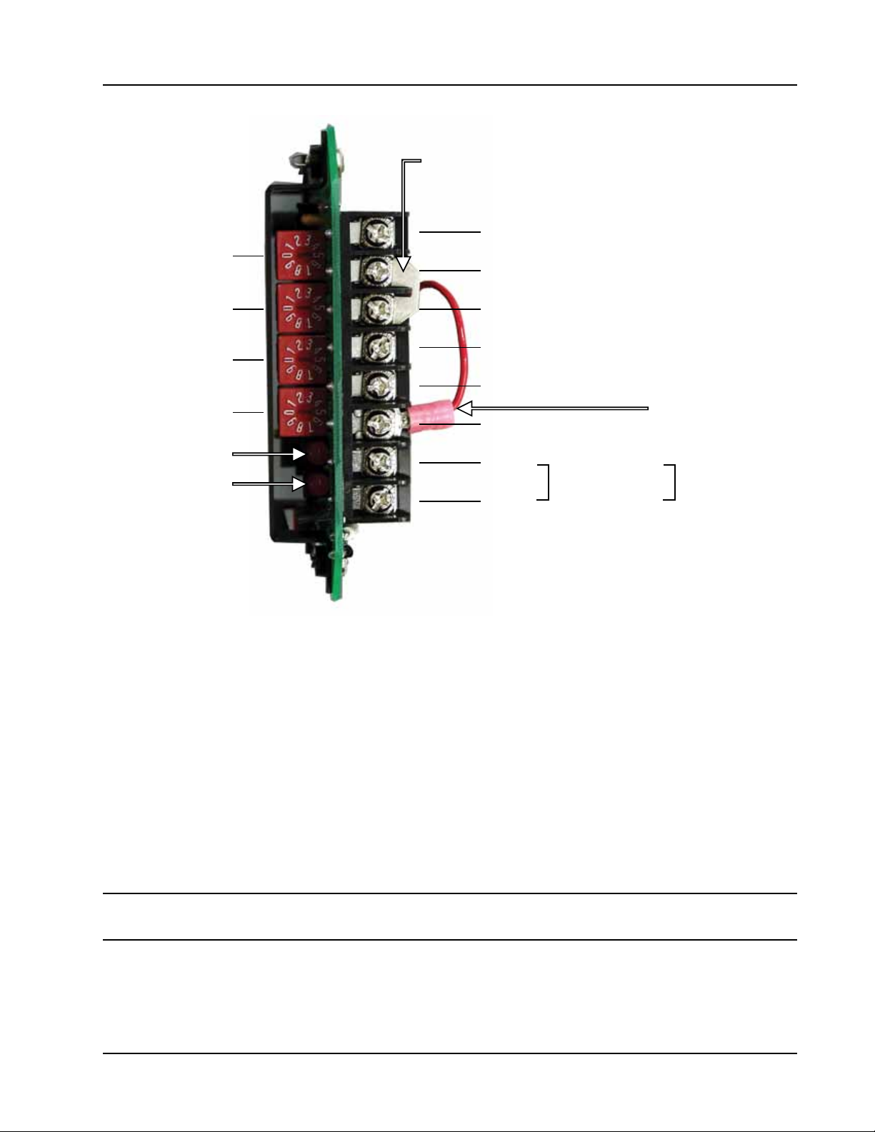
All eld connections are made to terminal block 1TB on the control card (Figure 2.2). Install wiring as
follows:
1. Connect power to 1TB-1 and 1TB-2.
2. Select the pulsed or repeat mode of operation as follows:
a. Connect jumper wire “E1” to 1TB-4 to select the repeat mode.
b. Connect jumper wire “E1” to 1TB-3 to select the pulsed mode of operation.
3. For pulsed mode operation, perform the following steps.
a. Wire the ow pulse input to 1TB-5 (signal) and 1TB-6 (common). The input pulse contact must be
closed for at least 5 msec to produce a start pulse. If an electronic square wave is utilized, it must have
a pulse amplitude of 12VDC. A 5VDC square wave will not work.
b. If input ow rates up to 10Hz are required, ensure a jumper is installed between 1TB-6 and 1TB-7 to
add lter capacitance to the ow pulse input circuit. This jumper must be removed when high fre-
quency ow rate signal inputs (10 to 1000 Hz) are required.
4. To power an external ow pulse circuit such as a turbine meter pre-amplier, connect the instrument to
the +12VDC output at 1TB-7. Maximum current from this supply is 50 mA.
9
CD-20A Sample Probe Controller
1TB-6 Pulse Input (Emitter) ( )-
1TB-5 Pulse Input (Collector (+)
1TB-4 (Repeat)
1TB-3 (Pulsed)
1TB-8 12VDC Output
1TB-7 Filter
Jumper required for input
flow rates up to 10 Hz; remove
jumper for rates of 10 to 1000 Hz
E1 jumper
for selecting mode
X1000 Switch
X100 Switch
X10 Switch
X1 Switch
I-Limit LED
PROX ( Holdî) LEDì
1TB-2 (-)
1TB-1 (+)
24VDC
Power
1TB-2 (N)
1TB-1 (H)
115VAC or
230VAC Power
Figure 2.2—Field wiring of CD-20A controller
Section 3—Maintenance
Operational Test
The start-up procedure consists of three steps: a repeat-mode checkout, an external input pulse mode
checkout, and a sample probe/control drive checkout. The following user-supplied equipment is required to
complete these tests:
• push-button switch
• power supply
• a 100-ml graduated beaker or other applicable measuring device
Note If the CD20A controller is connected to a sample probe, disconnect it before performing the following
procedures.

10
CD-20A Sample Probe Controller
Repeat Mode (Time-Proportional) Check-Out
To perform the repeat mode check-out,
1. Connect jumper E1 to terminal 1TB-4 (Figure 2.2, page 9).
2. Set the X10 switch to “6” and set the X1 switch to “0” to set a 60-second repeat time.
3. Apply input power to the CD-20A. Input power will be 12VDC, 24VDC, 115VAC or 230VAC, depending
on the controller model purchased.
4. Verify that the motor rotates 180 degrees and stops. This should take approximately 2.5 seconds. The
process should repeat at regular intervals as determined by the switch settings.
Note—Any input pulses that occur when the CD-20SFA is rotating are disregarded by the control logic.
5. Verify that the PROX (“Hold”) LED is on while the motor is stopped.The PROX (“Hold”) LED should be
off while the motor is running and turn on when the motor stops.
6. Verify the I-LIMIT LED blinks on momentarily during acceleration of the CD-20A motor. After the motor
reaches the 12 RPM running speed, the I-LIMIT LED should turn off.
7. Verify the CD-20A output shaft rotates in a clockwise direction as you look at the shaft. The sample probe
will rotate counterclockwise when the CD-20A controller is connected. If the direction of motor rotation
is wrong, swap the motor armature leads at 2TB-1 and 2TB-2.
External Pulse Mode (Flow-Proportional) Check-Out
1. Disconnect the input power from the CD-20A.
2. Move the E1 jumper to 1TB-3 to select the external pulse input mode (Figure 2.2, page 9).
3. Connect a push-button switch to 1TB-5 and 1TB-6.
4. Set the X1000, X100, and X10 switches to “0” and set the X1 switch to “1” to select a sample output for
each input pulse.
5. Apply power to the CD-20A.
6. Activate the switch to generate a pulse input to the motor control assembly. To be registered by the con-
trol logic, the input pulse must have a duration of 5 msec or longer and it must occur when the CD-20A
motor is stopped and the PROX (“Hold”) LED is on. The maximum valid ow proportional sampling rate
is 2.5 seconds per sample (24 samples/min).
7. Verify the CD-20A output shaft rotates 180 degrees for each external pulse.
Note—Any input pulses that occur when the CD-20A is rotating are disregarded by the control logic.
Sample Probe and CD-20A Check-Out
1. Disconnect input power from the CD-20A.
2. Mount the CD-20A to the sample probe and hand-tighten the DC-2 coupling.
3. Make sure the push-button switch is still connected to 1TB-5 and 1TB-6 (Figure 2.2, page 9).
Indice
Altri manuali Sensia Controllori


