Solartron Metrology BICM Series Manuale

BICM
(Boxed Inline Conditioning Module)
user leaet

Index
501651 Issue 13
Index
Section Title Page
Index . . . . . . . . . . . . . . . . . . . . . . . . . . 1
1.0 Introduction . . . . . . . . . . . . . . . . . 2
2.0 Technical Specification . . . . . . . . . . . . . . . 3
3.0 Operational and Set-Up Guide - BICM Kit . . . 6
3.1 Introduction . . . . . . . . . . . . . . . . . . . . . . 6
3.2 Screen Connection . . . . . . . . . . . . . . . . . 8
3.3 Gain Adjustment . . . . . . . . . . . . . . . . . . . 10
3.4 Offset . . . . . . . . . . . . . . . . . . . . . . . . 10
3.5 Set Up Using Fixed Value Resistors . . . . . 11
3.6 Gain Set Up Procedure . . . . . . . . . 13
3.7 Offset Set Up Procedure . . . . . . . . . 14
4.0 The Case . . . . . . . . . . . . . . . . . . . . . . . . . . 16
5.0 The "Why Doesn't it Work Guide" . . . . . . 17
6.0 Application Notes . . . . . . . . . . . . . . . . . . . . 18
6.1 Transducer Installation . . . . . . . . . . . . . . . . 18
6.2 Example 1 . . . . . . . . . . . . . . . . . . . . . 22
6.3 Example 2 . . . . . . . . . . . . . . . . . . . . . 23
Return Of Goods
Solartron Sales Offices
1

501651 Issue 13
1.0: Introduction & Glossary
The Boxed Inline Conditioning Module (BICM) is an electronics module that may be used with a wide range of LVDT transducers. Layout and size are
designed to allow the BICM to be easily fitted inline with the transducer cable and installed with the minimum of effort (or changed if ready connected to a
transducer)
The BICM output may be set for a full scale range up to ±10 VDC, offset facilities are provided. The BICM is either powered from a bipolar ±15 VDC supply
or a unipolar ±24 VDC supply depending on product type.
BICM - Boxed Inline Conditioning Unit
Gain - The output voltage per mm of transducer stroke
Offset - The output voltage when the transducer core is at null
P.C.B. - Printed Circuit Board
NPV - Nearest Preferred Value. A resistor selected from a standard range of value
(E24, E48, etc.) that is closest to the required value
BICM kits are supplied for user connection to an LVDT transducer.
2
1.0: Introduction
2.0: Introduction

501651 Issue 13
Standard BICM IP67 BICM
Bipolar Supply Unipolar Supply Bipolar Supply
Power Requirement
Voltage ±15 V ±1.5 V 24 V ±2.4 V ±15 V ±1.5 V
Current ±15 mA nominal 30 mA nominal ±15 mA nominal
Transducer Excitation
Primary Voltage 2 Vrms nominal
Primary Frequency 15 kHz typical
Primary Current 10 mA nominal
Signal Input
Input Voltage Range Up to 2.5 Vrms
Input Load Resistance 100 kW
3
2.0: Technical Specication
2.0: Technical Specication

501651 Issue 13
4
Standard BICM IP67 BICM
Bipolar Supply Unipolar Supply Bipolar Supply
Signal Output
Voltage Output Up to ±10 V
Current Output 11 mA
Output Ripple <14 mVrms
Output Offset 100%
Temp Co. Gain <0.03% FRO / oC
Temp. Co. Offset <0.025% FRO / oC
Warm up Time 15 minutes recommended
Linearity 2(electronics only) <0.1% FRO
Bandwidth (-3 dB) 3250 Hz typical
1Other frequencies are available on request.
2The electronics has a specification of <0.1%, the overall linearity is dominated by the transducer.
3Other bandwidths available on request.
4
2.0: Technical Specication
2.0: Technical Specication

501651 Issue 13
5
Standard BICM IP67 BICM
Bipolar Supply Unipolar Supply Bipolar Supply
Environmental
Operation Temperature Range 0 - 70 oC
Storage Temperature Range -20 to +85 oC
IP Rating IP40 IP67
Mechanical and Connections
Connections Solder pad or factory fit Factory fit only
Enclosure Size 98.5 x 30.5 x 13.0 mm 73.0 x 20.6 mm
Weight 30 g 75 g
Material ABS 400 Series Stainless Steel
Cable Lengths
All specification limits assume a nominal 3 m cable length between transducer and BICM. The BICM can be mounted up to 10 m from the transducer, but
this may result in reduced performance. Not all transducers can cope with long cable lengths. Cable from the BICM to the processing unit or display should
be limited to 100 m.
5
2.0: Technical Specication
2.0: Technical Specication

501651 Issue 13
3.1: Introduction
The BICM kit is supplied with a selection of potentiometers and an output cable allowing users to connect LVDT sensors and set up to their own
requirements. Connections are made to the BICM PCB as shown in Fig. 3.1A or Fig. 3.1B below depending on the PCB version.
The BICM output is adjustable for GAIN and OFFSET. See the specification for range of adjustments possible.
Gain is sometimes called span or range. This control will affect the output voltage at the full transducer stroke. Adjusting the control clockwise will increase
the output.
Offset is sometimes called DC shift or zero shift. This control may be used to zero the output if mechanically nulling the transducer is not convenient or
can provide as much as 100% offset to enable the output to be unipolar ie. 0V to 10 V for full transducer stroke. Adjusting the control clockwise will make
output more negative.
Adjustment is by means of trimmer potentiometers (also called variable resistor or pots). The BICM will accept fixed value resistors in place of
potentiometers.
The BICM is designed to accept the following types of potentiometer or resistor:-
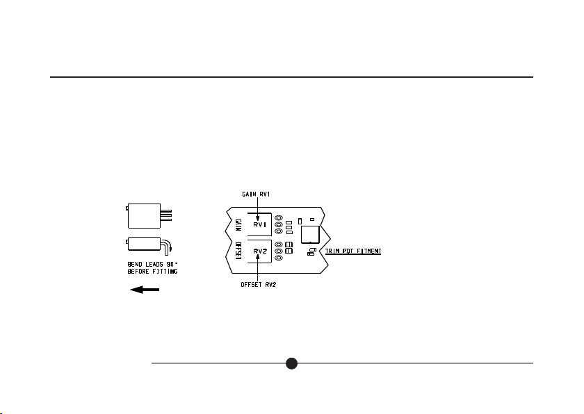
Potentiometer - Standard 3/8in square top adjust type potentiometer, see Fig. 3.1 (ie. Bourns 3299 type). The BICM kit comes complete with four
potentiometers.
Resistors - 1/4W MRF4 style.
6
3.0: Operational and Set-Up Guide - BICM Kit
3.0: Operational Guide

501651 Issue 13
Fig. 3.1A Connections to PCB - 105186 (Bipolar or Unipolar)
Fig. 3.1B Connections to PCB - 103766 (Bipolar only)
7
3.0: Operational and Set-Up Guide - BICM Kit
3.0: Operational Guide
Yellow
SEC2
SEC1
Green
White
Screen
Primary
Blue
Red
I/O CONNECTIONS
PRI1
PRI2
Screen
VOUT
0V
-15 V
0V
+15 V
Power
Supply
Output
Signal
SEC2
SEC1
Green
White
Screen
Primary
Blue
Red
TRANSDUCER CONNECTIONS
I/O CONNECTIONS
PRI1
PRI2
Screen
VOUT
0V
-15 V
0V
+15 V
Power
Supply
Output
Signal
Yellow
White
Green
Blue
Red
0V (Signal
white
)
Secondary 2 Green
0V Supply
Green
+15 V Bipolar
+24 V Unipolar
Red
Vout Yellow
Gain Offset
R2
+R4
R3
-R4
RV2RV1
R2
R1
Secondary 1 White
Primary Exc 2 Red
Primary Exc1 Blue
-15V Bipolar only
Blue
Screen

501651 Issue 13
3.2: Screen Connection
The screen connection is arranged so that the transducer cable screen and I/O cable screen is connected and that some cable strain relief is
provided whilst setting up the board. Screens are not connected to 0V on the PCB. Screen and 0V may be connected on the PCB by using a wire
link or at the user connection end, for example at the PSU, but it all depends on the installation requirements.
Colours are for Solartron MACH 1 5 kHz Series transducers. Check individual transducer data sheets before connecting.
If a different polarity output is required secondary connections may be reversed. See application notes.
Centre Tap (CT), yellow wire, connection not required. Ensure no loose wires.
3.2 Screen Connection
Fit the potentiometers in the positions indicated in Fig. 3.3. The table below gives suggested values for use with some solartron LVDT's. Once fitted
the set up procedure can be followed to give the required output.
8
3.0: Operational and Set-Up Guide - BICM Kit
FIG 4.2 SCREEN CONNECTION
3.0: Operational Guide
501651 Issue 13
9
3.0: Operational and Set-Up Guide - BICM Kit
3.0: Operational Guide
TRANSDUCER POTENTIOMETER VALUE (ohms)
GAIN OFFSET
B2.5 100K 5K
B5.0 50K 10K
B10 100K 5K
B15 100K 5K
B25 100K 5K
B50 50K 10K
B100 50K 10K
Fig. 3.3 Component Installation
Top View
Side View
Fit this way round
FIG 5.1 COMPONENT INSTALLATION
Transducer
Connection
End
Questo manuale è adatto per i seguenti modelli
2
Indice
Manuali Unità di controllo popolari di altre marche

Festo
Festo Compact Performance CP-FB6-E Manuale elenco delle parti

Elo TouchSystems
Elo TouchSystems DMS-SA19P-EXTME Manuale utente

JS Automation
JS Automation MPC3034A Manuale utente

JAUDT
JAUDT SW GII 6406 Series Guida rapida

Spektrum
Spektrum Air Module System Manuale utente

BOC Edwards
BOC Edwards Q Series Manuale utente


