www.spectronixinc.com Page Eye-BERT 100G User’s Guide V 0.2
8
Configurations
The following configurations are supported by the Eye-BERT 100G.
Output / Function
Description Pattern
Detector SMAa SMAb SFP QSFP
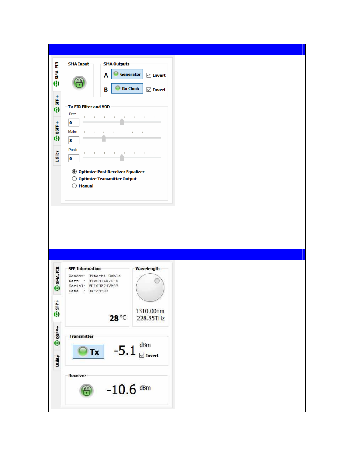
SMA BERT
2
SMA Generator
Rx clock
SMA BERT – SFP Gen SMA SMAin Tx clock Generator
SMA BERT – QSFP Gen SMA Tx clock Rx clock Generator
SFP BERT, Tx clock
2
SFP Tx clock SFPin Generator
SFP BERT, Rx clock SFP Rx clock
1
SFPin Generator
SFP BERT – SMA Gen, Rx clock SFP Generator
Rx clock SFPin
SFP BERT – SMA Gen, Tx clock SFP Generator
Tx clock SFPin
SFP BERT – QSFP Gen SFP Tx clock Rx clock Generator
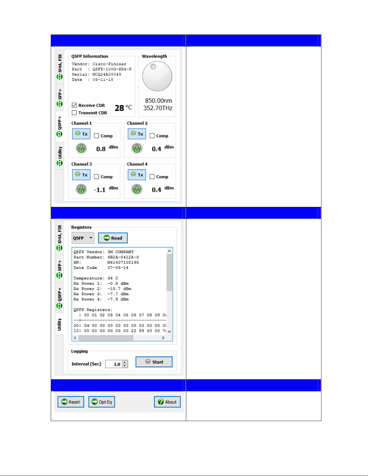
QSFP BERT
2, 3
QSFP Tx clock Generator
QSFP BERT – SMA Gen QSFP Tx clock Generator
QSFP BERT – SFP Gen QSFP Tx clock Generator
Media Converter
SFP CDR
1
- SMA clk
SFP clk
SFPin
SFPin
SMAin
SFPin
SMA CDR - SMA clk
SMAin
1. Requires connection from SMAb to SMA input.
2. Standard configuration
3. See QSFP BERT Mode discussion below
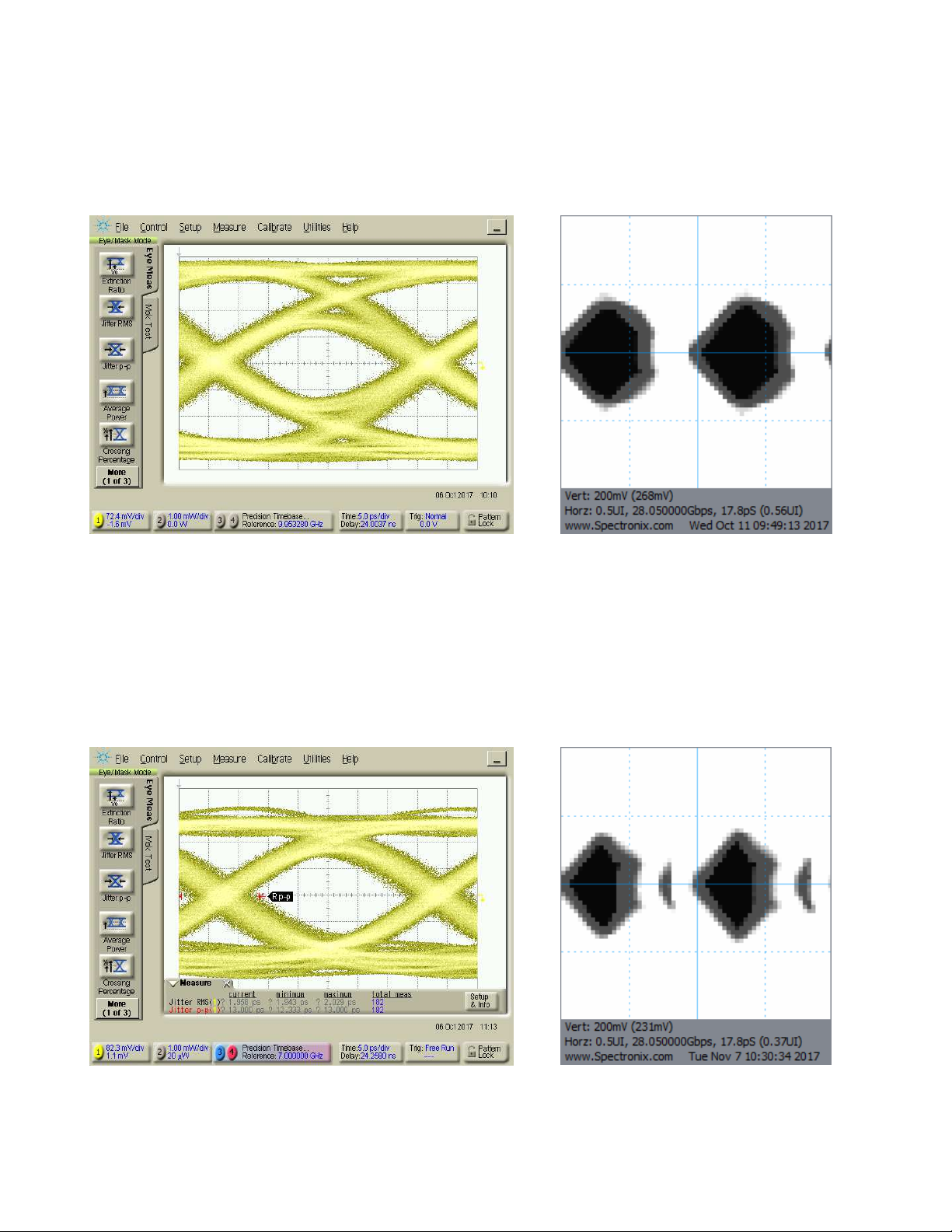
BERT Testing
The pattern generator utilizes normally inverted PRBS patterns in the range of 2
7
through 2
63
for
testing, however each output can be individually inverted to allow for testing with either polarity. The
BERT input signal does not need to be synchronous with its own generator and can be used with
PRBS signals from other equipment as long as the rate is within its lock in tolerance. Additionally the
Eye-BERT 100G will identify and lock onto any supported PRBS signal and polarity without having
configure its generator for a particular pattern. These features enable maximum flexibility and allow
remote testing with a separate generator. The test time reflected on the user interface is a calculation
of actual test time ( bits tested * bit rate ); for this reason, the test time will always be less than or
equal to the elapsed time since starting the test.
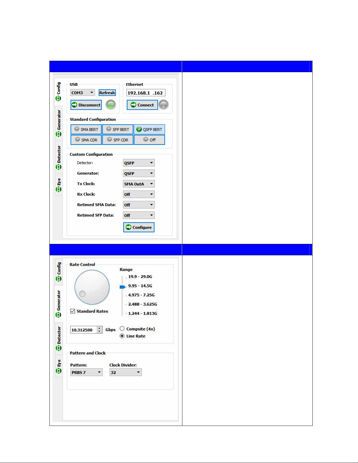
QSFP BERT Mode
Due to the internal clocking structure, special provisions should be observed when in QSFP BERT
mode. Channel 4 must be locked and receiving a PRBS signal in order to transmit on channel 1 and
channel 3 must be locked and receiving a PRBS signal in order to transmit on channel 2. If either
channels 3 or 4 become unlocked, channels 2 or 1 will also stop transmitting and loose lock.
If equipped, the transmit and receive CDRs inside the QSFP can be enabled or disabled using the
software application; the optimal settings depend on the transceiver capabilities and the application.
Some QSFP CDRs are narrow band and may only support a single data rate; disabling the CDRs