Toa SR-T5 Manuale utente

OPERATING INSTRUCTIONS
LINE ARRAY SPEAKER
WALL PAN BRACKET (optional)
SR-T5
SR-PB5
Thank you for purchasing TOA's Line Array Speaker.
Please carefully follow the instructions in this manual to ensure long, trouble-free use of your equipment.

2
TABLE OF CONTENTS
1. SAFETY PRECAUTIONS ................................................................................. 3
2. GENERAL DESCRIPTION .............................................................................. 5
3. FEATURES ........................................................................................................... 5
4. NOMENCLATURE AND DIMENSIONAL DIAGRAMS
4.1. SR-T5 Line Array Speaker
4.1.1. Speaker .................................................................................................... 6
4.1.2. Mounting Bracket A (accessory) .............................................................. 6
4.1.3. Mounting Bracket B (accessory) .............................................................. 6
4.2. SR-PB5 Wall Pan Bracket (Optional)
4.2.1. Pan bracket A (Quantity: 2) ...................................................................... 7
4.2.2. Pan bracket B (Quantity: 2) ...................................................................... 7
5. INTERNAL WIRING DIAGRAM AND
INPUT OVER-VOLTAGE PROTECTION CIRCUITRY ............................ 7
6. INPUT TERMINAL CONNECTION ............................................................... 8
7. CHANGING TO HIGH IMPEDANCE ............................................................ 9
8. BEFORE INSTALLING THE SPEAKER
8.1. Anchor Bolt Mounting Dimensions ................................................................... 12
8.2. Speaker Cable Outlet Position When Installing the SR-T5 Flat against Wall .. 12
9. MOUNTING TO THE WALL
9.1. When Installing the SR-T5 Using the Supplied Mounting Bracket Only
(Downward angle adjustable)
9.1.1. Coverage area ....................................................................................... 13
9.1.2. Rough installation plan ........................................................................... 14
9.1.3. Installation procedure ............................................................................. 14
9.2. When Installing the Speaker in Conjunction with the Optional SR-PB5
(Both horizontal and downward angles adjustable)
9.2.1. Rough installation plan ........................................................................... 18
9.2.2. Installation procedure ............................................................................. 18
10. SPECIFICATIONS
10.1. SR-T5 Line Array Speaker ............................................................................. 24
10.2. SR-PB5 Wall Pan Bracket (optional) .............................................................. 24

3
When Installing the Unit
• Refer all installation work to the dealer from whom the speaker was purchased. Installation requires
extensive technical knowledge and experience. The speaker may fall off if incorrectly installed, resulting in
possible personal injury.
• Install the unit only in a location that can structurally support the weight of the unit and the mounting bracket.
Doing otherwise may result in the unit falling down and causing personal injury and/or property damage.
• Since the unit is designed for in-door use, do not install it outdoors. If installed outdoors, the aging of parts
causes the unit to fall off, resulting in personal injury. Also, when it gets wet with rain, there is a danger of
electric shock.
• Owing to the unit's size and weight, be sure that at least two persons are available to install the unit. Failure
to do so could result in personal injury.
• Do not use other methods than specified to mount the bracket. Extreme force is applied to the unit and the
unit could fall off, possibly resulting in personal injuries.
• Attach the safety wire to the unit. If not attached, the unit could fall off, resulting in personal injury.
• Use bolts and nuts that are appropriate for the wall's material and structure. Failure to do so may cause the
unit to fall, resulting in material damage and possible personal injury.
• Tighten each nut and bolt securely. Ensure that the bracket has no loose joints after installation to prevent
accidents that could result in personal injury.
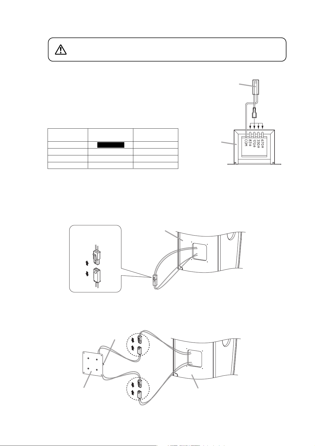
• Use the specified mounting bracket and matching transformer in combination. Doing otherwise may cause
the unit to fall off or generate heat, resulting in personal injury or fire.
• Do not mount the unit in locations exposed to constant vibration. The mounting bracket can be damaged by
excessive vibration, potentially causing the unit to fall, which could result in personal injury.
• Avoid installing the speaker in indoor swimming facilities that are not well ventilated. In such locations, the
bracket may be vulnerable to corrosion, eventually allowing the speaker to fall resulting in personal injury.
1. SAFETY PRECAUTIONS
• Before installation or use, be sure to carefully read all the instructions in this section for correct and safe
operation.
• Be sure to follow all the precautionary instructions in this section, which contain important warnings and/or
cautions regarding safety.
• After reading, keep this manual handy for future reference.
Safety Symbol and Message Conventions
Safety symbols and messages described below are used in this manual to prevent bodily injury and property
damage which could result from mishandling. Before operating your product, read this manual first and
understand the safety symbols and messages so you are thoroughly aware of the potential safety hazards.
Indicates a potentially hazardous situation which, if mishandled, could
result in death or serious personal injury.
WARNING

4
When Installing the Unit
• When unpacking or moving the unit, be sure to handle it with two or more persons. Falling or dropping the
unit may cause personal injury and/or property damage.
• Avoid touching the unit's sharp metal edge to prevent injury.
When the Unit is in Use
• Do not place heavy objects on the unit as this may cause it to fall or break which may result in personal
injury and/or property damage. In addition, the object itself may fall off and cause injury and/or damage.
• Do not operate the unit for an extended period of time with the sound distorting. Doing so may cause the
connected speakers to heat, resulting in a fire.
• Do not stand or sit on, nor hang down from the unit as this may cause it to fall down or drop, resulting in
personal injury and/or property damage.
• Have the unit checked periodically by the shop from where it was purchased. Failure to do so may result in
corrosion or damage to the unit or its mounting bracket that could cause the unit to fall, possibly causing
personal injury.
• Avoid connecting to an 83 Ωtap when using the speaker on high impedance 100 V line. Otherwise, heat
builds up in the matching transformer, possibly causing a fire.
Indicates a potentially hazardous situation which, if mishandled, could
result in moderate or minor personal injury, and/or property damage.
CAUTION

5
2. GENERAL DESCRIPTION
The TOA SR-T5 is a 2-way line array speaker in which low- and high-frequency speaker units are arranged
vertically within close proximity to each another. Its excellent speech clarity and sturdy impact-resistant
construction make it ideal for installation in sports facilities with strong reverberation, such as school
gymnasiums.
3. FEATURES
• Two-way line array speaker employs 8 of 13 cm (5.12") woofers and 24 of small tweeters.
• Curved vertical speaker arrangement covers entire audience area with uniform sound volume from front to
rear.
• Since the spread of speaker sound is suppressed in the vertical direction, the speaker is not subject to the
influence of rear wall or ceiling, allowing clear audio output even in spaces with poor acoustic conditions due
to long reverberation.
• Sturdy impact-resistant construction allows the speaker to be used without requiring additional protector
grilles, even in gymnasiums.
• Internal two-way passive crossover network circuitry adaptable to single-amplifier operation.
• Supplied mounting bracket permits the speaker’s downward angle to be adjusted by 1°, 2°, or 3° from the 0°
position (where mounted flat to a wall). Additional use of the optional SR-PB5 Wall Pan Bracket permits
either 5 ° or 10° left or right in horizontal angle adjustment.
• Optional MT-S0601 Matching Transformer permits use in high-impedance applications.
• Safety wire supplied to prevent the speaker from falling during installation work and after installation.

6
4. NOMENCLATURE AND DIMENSIONAL DIAGRAMS
4.1. SR-T5 Line Array Speaker
4.1.1. Speaker
4.1.2. Mounting Bracket A (accessory) 4.1.3. Mounting Bracket B (accessory)
[Top]
[Front] [Side] [Rear]
Used for temporarily suspending the speaker
at installation.
(Refer to p. 15 and p. 21.)
Unit: mm (inches)
M10 Nut (for suspension use)
310 (12.2)
99 (3.9)
341 (13.43)
1239 (48.78)
1167 (45.94)
Recess
Side cover
(Input terminal section)
Side cover
(Mounting Bracket B
joint section)
Side cover
(Mounting Bracket A
joint section)
Safety wire mounting bolts
Use either of 2 bolts.
(Refer to p. 12.)
Blank panel
(The optional MT-S0601
Matching Transformer can
be installed inside.)
Input terminal
2.6 (0.1)
145 (5.71)
Unit: mm (inches)
273.2 (10.76)
213 (8.39)
173 (6.81)
4 - ø10 (0.39)
4 - ø12 (0.47)
50
(1.97)
80
(3.15)
For anchor bolt
(Refer to p. 12 and p. 15.)
Use this hole to joint the optional SR-PB5
Wall Pan Bracket. (Refer to p. 18.)
2.6 (0.1)
Unit: mm (inches)
273.2 (10.76)
213 (8.39)
173 (6.81)
50
(1.97)
80
(3.15)
90
(3.54)
4 - 10 x 12 (0.39 x 0.47)
4 - 12 x 14 (0.47 x 0.55)
For anchor bolt
(Refer to p. 12 and p. 15.)
Use this hole to join the optional SR-PB5
Wall Pan Bracket. (Refer to p. 18.)

7
5. INTERNAL WIRING DIAGRAM AND INPUT OVER-VOLTAGE
PROTECTION CIRCUITRY
The internal wiring from the input terminal to the speaker units is as shown below.
4.2. SR-PB5 Wall Pan Bracket (Optional)
4.2.1. Pan bracket A (Quantity: 2) 4.2.2. Pan bracket B (Quantity: 2)
(1.97)
50
265 (10.43)
213 (8.39)
4 - ø12 (0.47)
For anchor bolt (Refer to p. 12 and p. 19.)
(4.22)
107.2
2.6 (0.1)
(2.24)
57
Unit: mm (inches)
Horizontal angle adjustment hole (for 5°)
Horizontal angle adjustment hole (for 10°)
(1.97)
50
(1.97)
50
4 - M8
Unit: mm (inches)
249 (9.8)
173 (6.81)
(4)
101.5
Use this hole to join the bracket supplied
with the SR-T5. (Refer to p. 18.)
2.6 (0.1)
Input
terminal
Interlocked connectors for
the matching transformer Network pc board
About the input over-voltage
protection circuitry
The speaker system has a built-in input
over-voltage protection circuitry for the
tweeters. If an excessive input signal is
applied to the speaker, the protection
circuitry works to cut off the signal input
to the tweeters.
A sudden drop of the volume level in
high frequencies during speaker
operation indicates that the over-
voltage protection circuitry has been
activated. In such a case, reduce the
amplifier volume and wait.
The protection circuitry is automatically
reset in approximately 10 seconds.
After the situation returns to normal, set
the volume at a level lower than before.

8
6. INPUT TERMINAL CONNECTION
Speaker
Input terminal
(on the side)
21
1
Speaker
cable
Speaker
cable
Cable entry hole (on the rear)
Input
terminal
Cable
entry hole
Pull the cable to take up
the slack after connection
completion.
Step 1. Run the speaker cable through the cable entry hole in the speaker's rear panel, then lead it out from
the side panel.
Pull out the cable slightly longer than needed from under the input terminal for ease of wiring.
Step 2. Connect the speaker cable to the input terminal.
Pull the speaker cable from the speaker's rear side to take up the slack.
Note
Pay attention to the correct polarity at the time of connection.
Step 3. Attach the supplied side cover.
Input terminal section
Side cover
(accessory)
Machine screw M4 x 10 with washer
(accessory)

9
7. CHANGING TO HIGH IMPEDANCE
The speaker can be used for high-impedance application with the installation of the optional MT-S0601
Matching Transformer.
To install the MT-S0601 transformer, remove the blank panel on the speaker's rear panel.
Step 1. Remove 4 screws holding the blank panel and detach the panel.
Note
When removing the blank panel, do not forcibly pull it since the interlocked connectors used to
connect the matching transformer is tied to the blank panel's back side.
Speaker (rear panel)
Blank panel
Machine screw
M4 x 25
Step 1. Mount the optional MT-S0601 Matching Transformer to the back side of the blank panel with the
machine screws and nuts attached to the blank panel.
Note
Use 2 screw holes located diagonally opposite.
This screw and another at the diagonal position can also be used
for mounting the transformer.
MT-S0601 Matching Transformer
(optional)
Blank panel
Machine screw M4 x 10
M4 nut

High impedance
70 V line
60 W
30 W
15 W
7.5 W
10
Step 3. Connect a lead wire to the desired impedance tap.
Step 4. Disconnect the lead wire connectors and connect them to the matching transformer.
4-1. Pull the connectors out of the speaker and disconnect the interlocked connectors.
4-2. Connect the removed connectors to the connectors from the transformer.
Never connect to an 83 Ωtap when using the speaker on
high impedance 100 V line. Otherwise, heat builds up in the
matching transformer, possibly causing a fire.
CAUTION
Note
Make wiring to the tap before installing the transformer
into the speaker. Note that the tap cannot be changed
from the outside once the transformer has been
installed.
The following table shows usable impedance.
Connector
(primary)
Red White
MT-S0601
(optional)
Primary
impedance
83 Ω
170 Ω
330 Ω
670 Ω
High impedance
100 V line
60 W
30 W
15 W
Unusable
Disconnect the
connectors.
Speaker
MT-S0601
Blank panel Speaker
Questo manuale è adatto per i seguenti modelli
1
Indice
Altri manuali Toa Altoparlanti


