ZT-1 User’s Manual – Installation
DOC #18172Page 4
Table of Contents
Limited Warranty ................................................................................................................5
Features Overview .............................................................................................................6
Specifications .....................................................................................................................8
Installation ........................................................................................................................10
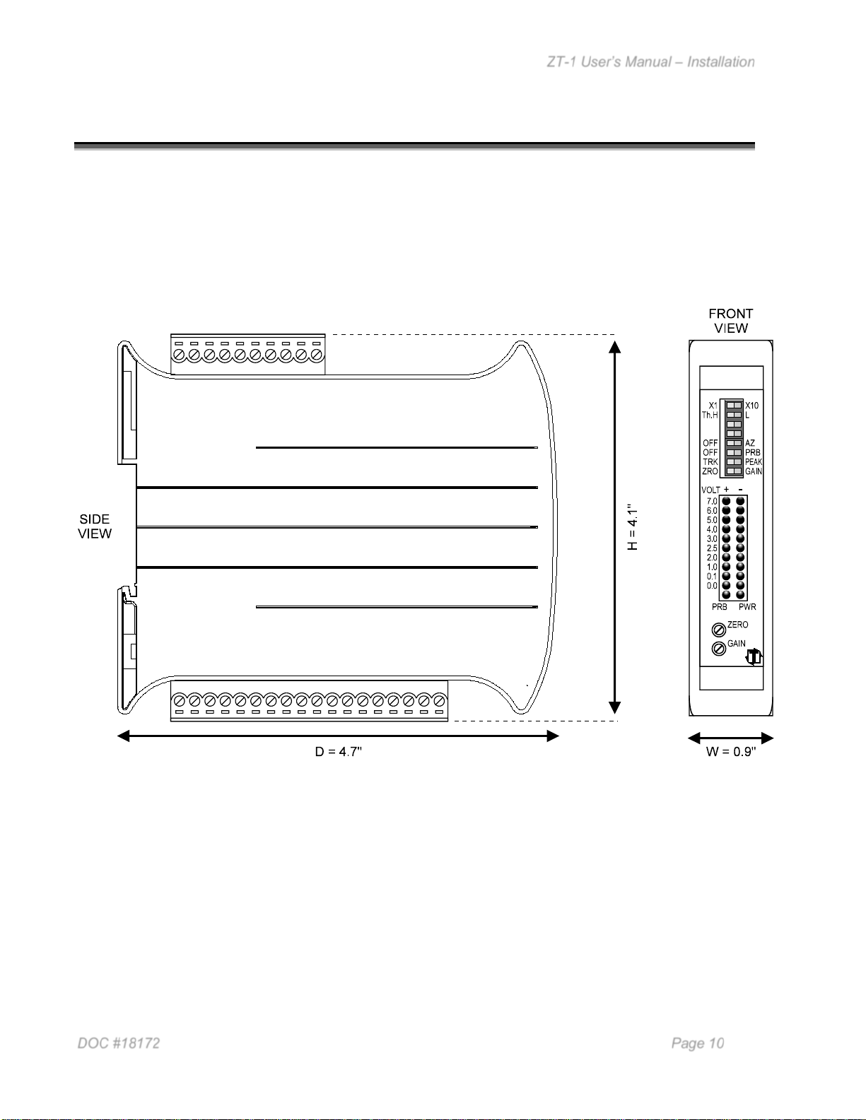
Mounting the ZT-1.........................................................................................................10
DC Power Connection...................................................................................................11
Shunt Resistor Selection...............................................................................................12
Strain Gage Load Cell / Sensor Connection .................................................................13
20mA-out Sensor Connection.......................................................................................17
10V-out Sensor Connection..........................................................................................18
Analog Voltage Output..................................................................................................19
Analog Current Output..................................................................................................20
Triggering – Internal Threshold.....................................................................................21
Triggering – External Probe..........................................................................................23
Calibration ........................................................................................................................25
Operation..........................................................................................................................30
Appendix...........................................................................................................................35
A) Sensor Installation (Doc# 11080) .......................................................................35
B) Calibration Sheets (2) (Form# 1224)..................................................................35
Table of Figures
Figure 1: Mounting Dimensions ...................................................................................10
Figure 2: DC Power Wiring ..........................................................................................11
Figure 3: Built-In 1M Ohm Shunt Resistor Wiring ......... Error! Bookmark not defined.
Figure 4: External Shunt Resistor Installation.............................................................12
Figure 5: Strain Gage Sensor Input .............................................................................14
Figure 6: Strain Gage Sensor Cable Stripping.............................................................15
Figure 7: Strain Gage Sensor Wiring ...........................................................................16
Figure 8: 20mA-out Sensor Input.................................................................................18
Figure 9: 10V-out Sensor Input...................................... Error! Bookmark not defined.
Figure 10: Analog Voltage Output Wiring.......................................................................19
Figure 11: Analog Current Output Wiring.......................................................................20
Figure 12: Internal Threshold Wiring..............................................................................22
Figure 13: Probe Input Wiring........................................................................................23
Figure 14: Probe Timing Diagram..................................................................................24
Figure 15: Calibration Gain Voltage Measurement........................................................28
Figure 16: Calibration Card Sample...............................................................................29