Tribe JETSPOT1 Manuale utente
USER MANUAL
MANUALE UTENTE
JETSPOT1
MOVING HEAD
EN - IT

All rights reserved by Music & Lights S.r.l. No part of this instruction manual may be
reproduced in any form or by any means for any commercial use.
In order to improve the quality of products, Music&Lights S.r.l. reserves the right to modify the
characteristics stated in this instruction manual at any time and without prior notice.
All revisions and updates are available in the ‘manuals’ section on site www.musiclights.it
REV.002-06/17

1
JETSPOT1
Packing content • JETSPOT1
• Mount bracket
• User manual
TABLE OF CONTENTS Safety
General instructions
Warnings and installation precautions
1 Introduction
1. 1 Description
1. 2 Technical specifications
1. 3 Operating elements and connections
2 Installation
2. 1 Mounting
3 Functions and settings
3. 1 Operation
3. 2 Basic
3. 3 Using the menu
3. 4 Menu structure
3. 5 Linking
3. 6 DMX mode
3. 7 DMX configuration
3. 8 DMX addressing
3. 9 Fixture settings
3. 10 Advanced
3. 11 Fixture information
3. 12 Operation in automatic mode
3. 13 Sensitivity microphone
3. 14 Connection of the DMX line
3. 15 Construction of the DMX termination
3. 16 DMX control
3. 17 Color
4 Maintenance
4. 1 Maintenance and cleaning the unit
4. 2 Fuse replacement
4. 3 Trouble shooting
2
2
3
3
5
6
7
7
8
8
9
9
9
10
11
12
13
13
13
14
14
15
17
18
18
19
JETSPOT1
2
WARNING! Before carrying out any operations with the unit, carefully read this instruction
manual and keep it with cure for future reference. It contains important information about
the installation, usage and maintenance of the unit.
SAFETY
General instruction
• The products referred to in this manual conform to the European Community Directives and are there-
fore marked with .
• The unit is supplied with hazardous network voltage (230V~). Leave servicing to skilled personnel only.
Never make any modifications on the unit not described in this instruction manual, otherwise you will
risk an electric shock.
• Connection must be made to a power supply system fitted with efficient earthing (Class I appliance ac-
cording to standard EN 60598-1). It is, moreover, recommended to protect the supply lines of the units
from indirect contact and/or shorting to earth by using appropriately sized residual current devices.
• The connection to the main network of electric distribution must be carried out by a qualified electrical
installer. Check that the main frequency and voltage correspond to those for which the unit is designed
as given on the electrical data label.
• This unit is not for home use, only professional applications.
• Never use the fixture under the following conditions:
- in places wet;
- in places subject to vibrations or bumps;
- in places with an ambient temperature of over 45°C.
• Make certain that no inflammable liquids, water or metal objects enter the fixture.
• Do not dismantle or modify the fixture.
• All work must always be carried out by qualified technical personnel. Contact the nearest sales point for
an inspection or contact the manufacturer directly.
• If the unit is to be put out of operation definitively, take it to a local recycling
plant for a disposal which is not harmful to the environment.
Warnings and installation precautions
• If this device will be operated in any way different to the one described in this manual, it may suffer
damage and the guarantee becomes void. Furthermore, any other operation may lead to dangers like
short circuit, burns, electric shock, etc.
• Before starting any maintenance work or cleaning the projector, cut off power from the main supply.
• Always additionally secure the projector with the safety rope.When carrying out any work, always com-
ply scrupulously with all the regulations (particularly regarding safety) currently in force in the country
in which the fixture’s being used.
• For inside use only. Not designed for outside use.
• The minimum distance between the fixture and surrounding walls must be more than 50 cm and the
air vents at the housing must not be covered in any case.
• Install the fixture in a well ventilated place.
• Keep any inflammable material at a safe distance from the fixture.
• The maximum temperature that can be reached on the external surface of the fitting, in a thermally
steady state, is high. After power off, please cool down over 15 minutes.
• Shields, lenses or ultraviolet screens shall be changed if they have become damaged to such an extent
that their effectiveness is impaired.
• The lamp (LED) shall be changed if it has become damaged or thermally deformed.
• Never look directly at the light beam. Please note that fast changes in lighting, e. g. flashing light, may
trigger epileptic seizures in photosensitive persons or persons with epilepsy.
• This product was designed and built strictly for the use indicated in this documentation. Any other use,
not expressly indicated here, could compromise the good condition/operation of the product and/or
be a source of danger.
• We decline any liability deriving from improper use of the product.

3
JETSPOT1
- 1 - INTRODUCTION
1.1 DESCRIPTION
JETSPOT1 is an extremely compact LED spotlight designed to deliver a bright, even beam from the small-
est footprint possible. Ideal where space is an issue, the JETSPOT1 simply offers the best value for money
in its segment with a light output far exceeding expectations. All packaged in a compact size and offered
at an affordable price.
1.2 TECHNICAL SPECIFICATIONS
LIGHT SOURCE
• Source: 18W high-power white LED
• CT: 7000K
• CRI: 73
• Luminous flux: 1288lm
• Lux: 2533lx @3 m
• Lux: 227.97lx @10 m
• Source life expectancy: >30.000 h
OPTICS
• Beam angle: 16°
• Lens type: high-quality glass lens optics
COLOUR SYSTEM
• Colour wheel: 9 dichroic filters + open
DYNAMIC EFFECTS
• Fixed gobos: 9 fixed gobos + open
• Auto mode: built-in programs with execution speed adjustment
• Sound mode: music activation through internal microphone and sensitivity control
BODY
• Pan angle: 540°
• Tilt angle: 270°
• Pan/Tilt resolution: 8 / 16 bit
• Feedback: automatic repositioning after accidental movement
• Body: aluminium structure with hi-resistance polycarbonate cover
• Body colour: black, white finishing available
CONTROL
• Protocols: DMX512, RDM
• DMX channels: 8 / 10channel
• W-DMX: optional, proprietary protocol compatible with WIFIBOX, WDBOX
• RDM: RDM ready for fixture remote monitor and settings
• Display: black OLED high resolution display
• Firmware upgrade: yes, via USB - DMX interface (UPBOX1) not included
• Master/Slave: for synchronized operation of more units linked in a chain

JETSPOT1
4
ELECTRONICS
• Dimmer: linear 0 ~ 100% electronic dimmer
• Strobe / shutter: 0~30 Hz, electronic
• Operating temperature: -10° ~ +45°
• Flicker: flicker free operation
ELECTRICAL
• Power supply: 100-240 V – 50/60 Hz
• Power consumption (at 230V): 40.6W
• Power consumption (at 120V): 39.7W
• Output (at 230V): 67 units on a single power line
• Output (at 120V): 37 units on a single power line
PHYSICAL
• Cooling: forced air with low noise fan
• Sospension and fixing: any position with quick-lock omega brackets
• Data: USB port for USB WIFI transmitter (optional)
• Signal connection: XLR 5p IN/OUT connectors
• Power connection: Seetronic powerCON IN/OUT connectors
• IP rating: 20
• Dimensions (WxHxD): 210x308x170mm
• Weight: 4.2kg
Fig.1
298
210 170
Technicaldrawing
5
JETSPOT1
34
6
5
1
2
A
B
78 9 10 11
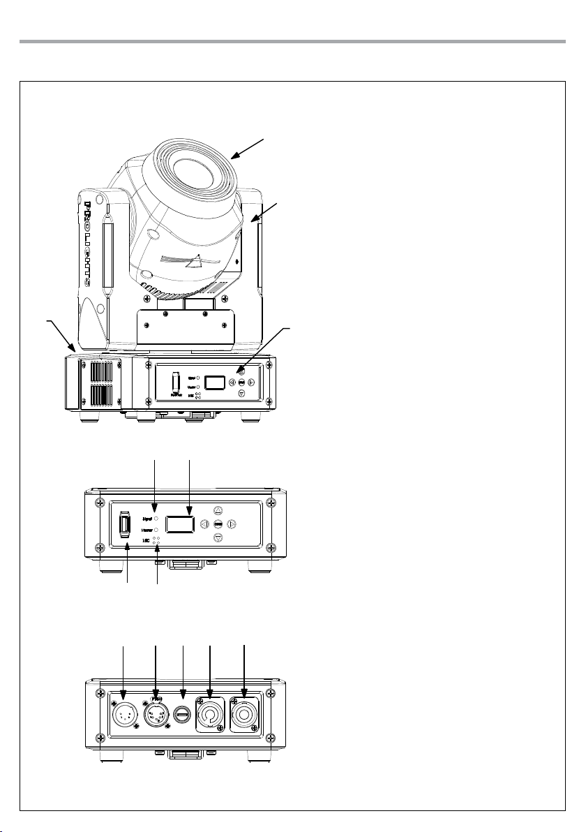
1.3 OPERATING ELEMENTS AND CONNECTIONS
Fig.2
1. MOVING HEAD
2. ROTARY ARM
3. CONTROL PANEL with LCD display
and 5 button used to access
the control panel functions and
manage them.
4. LED INDICATOR
5. Universal Serial Bus (USB)
6. MICROPHONE
7. DMX IN (XLR a 5 poli): 1 = massa, 2
= DMX -, 3 = DMX +, 4 N/C, 5 N/C
8. DMX OUT (XLR a 5 poli): 1= massa,
2 = DMX -, 3 = DMX +, 4 N/C, 5
N/C
9. MAIN FUSE HOLDER: replace a
burnt-out fuse by one of the same
type only.
10. POWER IN (PowerCON IN):
for connection to a socket
(100-240V~/50-60Hz) via the
supplied mains cable.
11. POWER OUT: (PowerCON OUT) to
connect multiple units in series.
View A
View B

JETSPOT1
6
- 2 - INSTALLATION
2.1 MOUNTING
The JETSPOT1 may be set up on a solid and even surface. By means of the fixing facilities of the baseplate,
the unit can also be mounted upside down to a cross arm. The base plate is shown in fig.3. For fixing, stable
mounting clips are required. According to the figure, the bolts of the brackets are placed into the openings
provided in the base plate and turned clockwise until they lock (to the stop). Always ensure that the unit
is firmly fixed to avoid vibration and slipping while operating. The mounting place must be of sufficient
stability and be able to support a weight of 10 times of the unit’s weight. When carrying out any installa-
tion, always comply scrupulously with all the regulations (particularly regarding safety) currently in force
in the country in which the fixture’s being used. Always additionally secure the projector with the safety
rope from falling down. For this purpose, fasten the safety rope at a suitable position so that the maximum
fall of the projector will be 20 cm.
Fig.3
CLAMP
SAFETY
CABLE
OMEGA
BRACKETS

7
JETSPOT1
- 3 - FUNCTIONS AND SETTINGS
3.1 OPERATION
Connect the supplied main cable to a socket (100-240V~/50-60Hz). The unit will run built-in program to
reset all motors to their home position. Shortly after that the JETSPOT1 is ready for operation. To switch
off, disconnect the mains plug from the socket. For a more convenient operation it is recommended to
connect the unit to a socket which can be switched on and off via light switch.
3.2 BASIC
The control panel of JETSPOT1 has a display and 5 buttons for the complete programming and manage-
ment of the projector menu (fig.4).
Fig.4 - Functions of the buttons
Enter
UP DOWN LEFT RIGHT ENTER
Increases the value
displayed or passes to
the previous item in a
menu
Decreases the value
displayed or passes to
the next item in the
menu
To enter in the main
menù or to return to the
top level
Commute from units,
tens, hundred in the
menu
Confirms the displayed
value, or activates the
displayed function, or
enters the successive
menu
Reversal of the display
To activate this function, hold simultaneously for 3 seconds UP and DOWN buttons while the display
is in the rest mode. This status will be memorised and maintained even for the next time it will be
switched on.
To return to the initial state, repeat the operation all over again.

JETSPOT1
8
3.3 USING THE MENU
1. Press the ENTER button to access the main menu.
2. Use the UP/DOWN button to select the menu to be used:
• Connect;
• Setup;
• Advanced;
• Information;
• Stand alone;
3. Press ENTER to display the first item in the selected menu.
4. Use the UP/DOWN button to select the menu items.
NOTE -The display can be in one of two conditions: rest status and setting status. When it is in the rest sta-
tus, the display shows the projector’s DMX address. During menu setting status, after a wait time without
any key having been pressed, the display automatically returns to rest status.
It should be noted than when this condition occurs, any possible value that has been modified but not yet
confirmed with the ENTER button will be cancelled.
3.4 MENU STRUCTURE
MENU
1CONNECT ðDMX Address ðValue (1-512)
DMX Mode ðBasic 8-8CH
Basic 16-10CH
2SET UP ðMovement ðPan Reverse ðYES/NO
Tilt Reverse ðYES/NO
Screen ðBacklight ðON
10s
20s
30s
Flip Display ðYES/NO
Warn Cue ðON/OFF
Key Lock ðON/OFF
Auto Test ðAuto Test
Manual Test ðPan
Pan Fine
Tilt
Tilt Fine
Pan/Tilt Speed
Dimmer
Shutter
Color
Gobo
ðValue (000-255) for each function
Questo manuale è adatto per i seguenti modelli
2
Indice
Lingue:
Altri manuali Tribe Attrezzatura per DJ

Tribe
Tribe PROLIGHTS SMARTBATTENQ Manuale utente

Tribe
Tribe SUNRISE2 Manuale utente

Tribe
Tribe MINIVERSAPAR Manuale utente

Tribe
Tribe JETSPOT3 Manuale utente

Tribe
Tribe LUMIPAR12UH3P Manuale utente

Tribe
Tribe Crystal Manuale utente

Tribe
Tribe JETBEAM1 Manuale utente

Tribe
Tribe PIXROLL10UTRI Manuale utente

Tribe
Tribe BATGOBOIR Manuale utente

Tribe
Tribe FLATPAR3Q Manuale utente


