www.trikdis.com 2 October, 2023
Contents
1 DESCRIPTION ............................................................................................................................................................. 4
1.1 List of compatible control panels .......................................................................................................................... 5
1.2 Communicator model types .................................................................................................................................. 5
1.3 Specifications ........................................................................................................................................................ 5
1.4 Communicator elements ....................................................................................................................................... 6
1.5 Purpose of terminals ............................................................................................................................................. 6
1.6 LED indication of operation ................................................................................................................................... 6
1.7 Structural schematic of using the GET communicator .......................................................................................... 7
2 QUICK CONFIGURATION WITH TRIKDISCONFIG SOFTWARE .................................................................................................... 8
2.1 Settings for connection with Protegus app ........................................................................................................... 8
2.2 Settings for connection with Central Monitoring Station ................................................................................... 10
3 INSTALLATION AND WIRING ......................................................................................................................................... 12
3.1 Installation process ............................................................................................................................................. 12
3.2 Schematics for wiring the communicator to the serial or keypad bus of the control panel................................ 13
3.3 Schematic for wiring the communicator to the control panel keyswitch zone ................................................... 14
3.4 Schematics for wiring the communicator to the telephone line of the control panel ......................................... 14
3.5 Schematics for input connection ......................................................................................................................... 15
3.6 Schematics for wiring a relay .............................................................................................................................. 15
3.7 Schematics for connecting iO-8 expansion modules ........................................................................................... 15
3.8 Turn on the communicator ................................................................................................................................. 16
4 PROGRAMMING THE CONTROL PANEL ............................................................................................................................ 16
4.1 Programming of control panels when the communicator is connected to the keypad bus or serial bus ........... 16
4.2 Programming of control panels when the communicator is connected to the TIP/RING terminals of the control panel
....................................................................................................................................................................... 17
5 REMOTE CONTROL .................................................................................................................................................... 19
5.1 Adding the security system to Protegus app ....................................................................................................... 19
5.2 Additional settings to arm/disarm the system using the control panel’s keyswitch zone .................................. 20
5.3 Arming/disarming the alarm system with Protegus ........................................................................................... 22
6 TRIKDISCONFIG WINDOW DESCRIPTION .......................................................................................................................... 22
6.1 TrikdisConfig status bar description .................................................................................................................... 22
6.2 “System settings” window .................................................................................................................................. 23
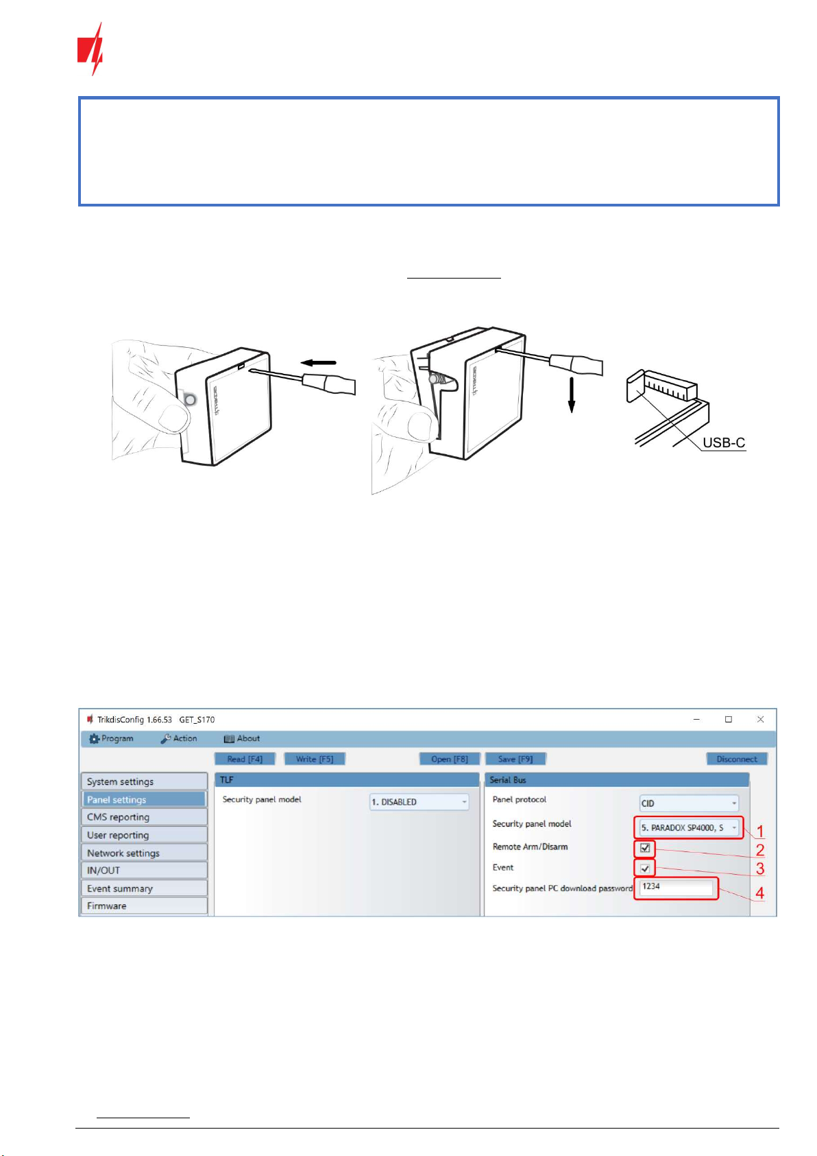
6.3 “Panel settings” window ..................................................................................................................................... 24
6.4 “CMS reporting” window .................................................................................................................................... 26
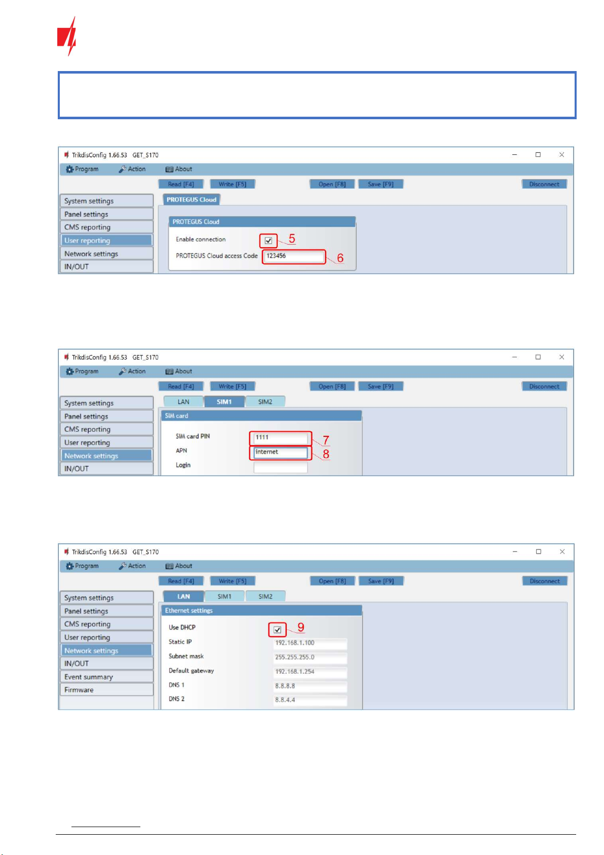
6.5 “User reporting” window .................................................................................................................................... 27
6.6 “Network settings” window ................................................................................................................................ 28
6.7 “IN/OUT” windows.............................................................................................................................................. 30
6.8 “RS485 modules” window ................................................................................................................................... 30
6.9 “Event summary” window .................................................................................................................................. 32
6.10 Restoring factory settings ................................................................................................................................... 32
7 REMOTE CONFIGURATION ........................................................................................................................................... 32
8 TEST COMMUNICATOR PERFORMANCE ........................................................................................................................... 33
9 FIRMWARE UPDATE ................................................................................................................................................... 33
10 ANNEX ................................................................................................................................................................... 35